Page 1
American Journal of Civil Engineering 2025, Vol. 13, No. 4, pp. 245-256 https://doi.org/10.11648/j.ajce.20251304.16 Research Article Comparative Analysis of Structural Response of Multi-storey Reinforced Concrete Framed Building with Different Infill Wall Materials Bimal Ojha1, Prabin Pokharel1, Sabin Khatri1, Padam Karki1, Binaya Jamarkattel1, Abhinesh Khatri2, Hari Ram Parajuli3, * 1Department of Civil Engineering, Institute of Engineering Thapathali Campus, Kathmandu, Nepal 2Department of Civil Engineering, Kantipur Engineering College, Lalitpur, Nepal 3Department of Civil Engineering, Institute of Engineering Pulchowk Campus, Kathmandu, Nepal Abstract This study evaluates the seismic performance of reinforced concrete (RC) frame structures with different infill materials using analytical modeling techniques. Five types of infill- common brunt clay bricks, AAC blocks, gypsum board, lime-based solid blocks, hollow concrete blocks -were considered to assess their impact on key seismic response parameters such as base shear, displacement, time period, and minimum beam-column sizes. Finite element modeling was performed using ETABS v20, with infills idealized as equivalent diagonal struts based on their material properties and stiffness characteristics. Response spectrum analysis were employed to simulate structural behavior under seismic loading. Results show that brick-infilled frames and concrete blocks exhibit higher stiffness but also higher seismic mass, resulting in increased base shear and structural member sizes. AAC blocks significantly reduce base shear and fundamental time period due to their light weight, though they lead to increased lateral displacement. Lime-based solid blocks demonstrated a balanced performance, offering reduced seismic demand, moderate stiffness, and controlled displacements while maintaining sustainable construction benefits. The overall analysis demonstrates that the lighter infill materials like AAC and gypsum reduce base shear, they may permit excessive lateral deformation. Conversely, denser materials improve lateral stiffness but increase seismic demand. Therefore, in earthquake-prone regions like Nepal, where both seismic safety and cost-efficiency are vital, the infill wall material must be selected based on a balance between displacement control and seismic force minimization. Further research is recommended in areas such as effects on asymmetrical buildings, experimental validation, non-linear interaction modeling, and the development of hybrid infill systems for optimized structural and environmental outcomes. Keywords Infill Wall Materials, RCC Framed Building, Equivalent Diagonal Strut *Corresponding author: Received: 2 June 2025; Accepted: 4 June 2025; Published: 15 August 2025 Copyright: © The Author(s), 2025. Published by Science Publishing Group. This is an Open Access article, distributed under the terms of the Creative Commons Attribution 4.0 License (http://creativecommons.org/licenses/by/4.0/), which permits unrestricted use, distribution and reproduction in any medium, provided the original work is properly cited.

Page 2
American Journal of Civil Engineering http://www.sciencepg.com/journal/ajce
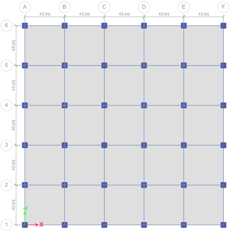
- Introduction Reinforced concrete (RC) framed structures are the most displacement, and base shear. Despite their structural influ- common form of construction in urban and semi-urban areas ence, infill walls are frequently treated as non-structural of Nepal, especially for residential, commercial, and institu- components and are often ignored in analytical models. tional buildings. In most cases, these frames are combined However, evidence from recent earthquakes, particularly the with masonry infill walls, typically made of clay bricks, 2015 Gorkha Earthquake, has shown that infill walls play a concrete blocks, or more recently, autoclaved aerated concrete crucial role in altering the dynamic characteristics of build- (AAC) blocks. While these infill walls are primarily intended ings [5, 6]. Unreinforced masonry Infills modify the behavior for partitioning and enclosing spaces, they inadvertently in- of framed structures under lateral loads; however, in practice, fluence the structural response of the building [1]. Traditional the infill stiffness is commonly ignored in frame analysis, materials such as fired clay bricks and concrete blocks offer resulting in an under-estimation of stiffness and natural fre- high stiffness and compressive strength; however, they also quency [7]. contribute to increased seismic mass, thereby amplifying base To capture the influence of infill walls in analysis, the shear forces during an earthquake [2]. In contrast, modern equivalent diagonal strut model is used which replaces the alternatives like autoclaved aerated concrete (AAC) blocks, infill panel with one or more diagonal compression-only struts gypsum boards, and lime-based solid blocks offer various between beam-column joints [8]. benefits such as reduced self-weight, enhanced thermal insu- In this study, a comparative analysis is performed using lation, and cost-effectiveness [3]. The light weight infill ETABS v20 software to model three multi-storey RC framed model is having significantly smaller base shear as compared buildings viz (G+2, G+5, G+8) with various types of masonry with other infill models which results in decrease in rein- infill walls. The infill is incorporated using the equivalent forcement to resist member forces, hence economy in con- diagonal strut approach. The study compares the seismic struction can be achieved [4]. responses-base shear, displacement, inter-storey drift, natural This research primarily focuses on reduced dead load on period, and storey stiffness-of buildings with five different RCC framed structure due to various infill wall alternatives infill materials such as common brunt clay bricks, AAC like common brunt clay bricks, AAC blocks, gypsum board, blocks, gypsum board, lime-based solid blocks, and hollow lime-based solid blocks, hollow concrete blocks etc as it di- concrete blocks. All analyses conform to seismic provisions rectly influences the dimensions of structural elements such as of the IS 1893: 2016 [9] and include modal and response beams and columns, as well as the building's time period, spectrum analysis. Figure 1. Plan of building. 246
Page 3
American Journal of Civil Engineering http://www.sciencepg.com/journal/ajce This research aims to provide insights into how infill ma- conditions. terial type affects overall structural performance by compar- ing base shear, displacement, and the required sizes of beams 3. Methodology and columns across different building heights and infill ma- terials which in results provide valuable insights into opti- In this study, a simplified square plan configuration of three mizing structural design for safety and efficiency in high different storey (G+2, G+5 and G+8) with dimensions of seismic zones. The findings will be valuable for structural 22.5m x 22.5m was used to model the building with exterior engineers and code developers in Nepal and other earth- brick walls of 230 mm thickness. The interior partition walls quake-prone regions with similar construction practices. are modeled with five different infill material viz common brunt clay bricks, AAC blocks, gypsum board, lime-based 2. Objectives solid blocks and hollow concrete blocks. It is assumed that all walls are non-load bearing, and their effects on the structural The objective of this research is to: response are considered negligible except for their contribu-
- Compare the structural parameters such as time period, tion to the dead load of the building. This means that while the maximum storey displacement and base shear across dead load from the infill walls is factored into the analysis, various infill materials in different storey buildings. other potential effects such as lateral load distribution and
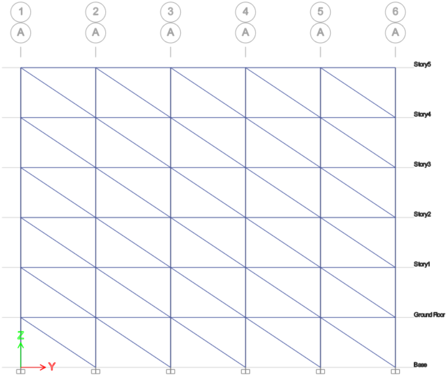
- Determine the minimum beam and column sizes re- interaction with the structural frame are not considered in this quired for different infill wall materials under standard study. Figure 2. Elevation of building (G+5) with diagonal strut model. A literature review was conducted to select various infill IS 875 Part 1 as well as from relevant research papers re- materials for the study. The densities of these infill materials viewed during the literature review. were determined based on the guidelines provided in IS Code The infill wall materials consider are as follows: 247
Page 4
American Journal of Civil Engineering http://www.sciencepg.com/journal/ajce Table 1. Showing properties of different infill wall materials as per IS 875: part 1) [10]. Infill Material Unit weight Advantages Disadvantages
- High durability and strength. 1) Heavier than many modern alternatives, Common burnt 2) Good thermal insulation properties. increasing the dead load on the structure. 19.2 kN/m3 clay Bricks 3) Widely available and well understood in con- 2) Manufacturing involves high energy con- struction practices. sumption and carbon emissions.
- Lightweight, reducing the dead load on the structure.
- Lower strength compared to traditional bricks.
- Excellent thermal and sound insulation proper- AAC Blocks 4.5 -5 kN/m3 2) Higher cost and limited availability in some ties. regions.
- Fire-resistant and easy to work with, leading to faster construction.
- Highly sustainable and environmentally 1) Lower compressive strength, making it un- friendly. suitable for load-bearing applications. Hempcrete 2.94 - 5.9 kN/m3
- Excellent thermal and acoustic insulation. 2) Requires protection from moisture, as it is
- Lightweight reducing the structural load. susceptible to water damage.
- Lightweight and easy to install.
- Not suitable for exterior use due to poor re-
- Provides a smooth finish suitable for painting or 7.3 - 10.27 sistance to moisture. Gypsum Board wallpapering. kN/m3
- Lower strength compared to traditional ma-
- Fire-resistant and provides good sound insula- sonry materials. tion.
- Durable and strong, suitable for load-bearing
- Heavier than some modern materials like AAC walls. blocks. Lime-Based Solid 8.65 - 12.55 2) Environmentally friendly, as lime production
- Requires skilled labor for proper construction, Blocks kN/m3 has a lower carbon footprint than cement. as the material has different handling proper-
- Good thermal properties and resistance to mold ties compared to cement. and pests. The loads considered during the study are as follows: 3) Seismic load [IS 1893 (part 1): 2016] [9].
- Dead load [IS 875(part 1): 1987] [10]. The structural modelling was done in ETABS v20 with the
- Live load [IS 875(part 2): 1987] [11]. following details: Table 2. Description of Building. Attribute Description Height of storey 3m Plinth area 22.5m*22.5m Slab thickness 150mm Grade of rebar Fe500 Grade of concrete M20 Live load on floor 3 kN\m2 248
Page 5
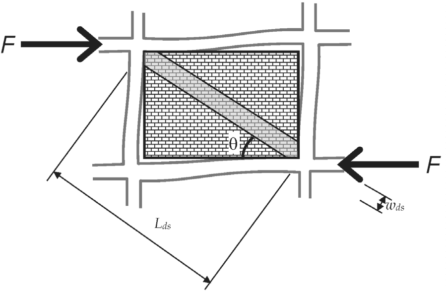
American Journal of Civil Engineering http://www.sciencepg.com/journal/ajce Table 3. Details of Seismic Parameters. Coefficient for Earthquake load Value Seismic Zone factor 0.36 Response reduction factor 5 Soil type Medium Importance factor 1 Table 4. Density of Infill wall material and Line Load. In-fill wall material Unit weight (kN/m3) Thickness of wall (m) Line load (kN/m) Bricks 19.2 0.115 6.62 AAC Blocks 5 0.15 2.25 Hempcrete 4.4 0.15 1.98 Gypsum Boards 8.785 0.03 0.79 Lime based solid blocks 10.6 0.1 3.18 A macro finite element (FE) modeling approach was adopted in this study to examine the effect of infill walls on w = 0.175 α-0.4 L ds ds the structural behavior of reinforced concrete (RC) structures. Specifically, the equivalent diagonal strut model was em- where, α = h 4 √𝐸𝑚∗ 𝑡∗ 𝑠𝑖𝑛2𝜃 ployed to simulate the infill walls. End releases were em- 4 𝐸𝑓∗𝐼𝑐∗ℎ ployed for the struts in ETABS v20 in order to realistically E and E are the moduli of elasticity of the materials of the m f simulate the behavior by having them subjected to only unreinforced masonry (URM) infill and reinforced concrete compressive loads and not tensile loads. The width of equiv- moment resisting frame (RC MRF) respectively, Ic is the alent diagonal strut is calculated according to IS 1893(part I): moment of inertia of the adjoining column, t is the thickness 2016 [9]. of masonry infill wall and θ is the angle of diagonal strut with the horizontal. Figure 3. Equivalent diagonal strut of URM infill wall (IS 1893: part -1: 2016). 249
Page 6
American Journal of Civil Engineering http://www.sciencepg.com/journal/ajce The modulus of elasticity E (in Mpa) of masonry infill tained after test as per IS 1905 or given by expression m wall is given by f = 0.433 f 0.64 f 0.36 m b mo E = 550 f m m where f and f are compressive strength of brick and mortar b mo where f is the compressive strength of masonry prism ob- respectively in MPa. m Table 5. Width of diagonal strut in mm for different infill materials and building configuration. Infill material Storey Width of diagonal strut in mm G+2 603 Hollow concrete blocks G+5 698 G+8 768 G+2 634 Common burnt clay bricks G+5 735 G+8 808 G+2 618 Gypsum partition block G+5 714 G+8 789 G+2 663 Lime based solid blocks G+5 766 G+8 845 G+2 618 AAC blocks G+5 712 G+8 791 conditions as per IS 1893 (part 1): 2016. The key performance parameters examined include fundamental time period, base 4. Results and Discussion shear, inter-storey drift, storey displacement, stress on beams and columns etc. Results are presented in tabular and graphical for- The structural response of multistorey RCC framed building mats, highlighting the comparative influence of each infill mate- modelled with different infill wall materials: common brunt clay rial on seismic behavior. bricks, AAC blocks, gypsum board, lime-based solid blocks and hollow concrete blocks is presented in this section. All models were analyzed using ETABS v20 under the seismic loading 4.1. Fundamental Time Period Table 6. Fundamental time period (in seconds) for different infill-wall materials and building configuration. SN Infill- Wall material G+2 G+5 G+8 1 Hollow concrete blocks 0.711 0.98 1.31 250
Page 7
American Journal of Civil Engineering http://www.sciencepg.com/journal/ajce SN Infill- Wall material G+2 G+5 G+8 2 Common brunt Clay Bricks 0.727 1.02 1.335 3 Gypsum partition block 0.751 1.039 1.362 4 Lime based solid blocks 0.753 1.042 1.368 5 AAC blocks 0.781 1.073 1.39 The fundamental time period of a structure is a key indi- 4.2. Optimal Beam and Column Sizes cator of its dynamic characteristics, directly influenced by its Requirement mass and stiffness. In this study, the time periods were ob- tained from modal analysis in ETABS for buildings with The selection of appropriate beam and column dimensions varying storey heights (G+2, G+5, and G+8) and different is critical for ensuring adequate strength, stiffness, and duc- infill wall materials. The results are summarized in Table 6. tility in reinforced concrete (RC) frames, particularly under As expected, the time period increased with the number of seismic loading. The presence and type of infill walls signif- storeys, owing to the increased mass and flexibility. For each icantly influence these requirements by altering the distribu- storey level, the type of infill wall significantly influenced the tion of lateral forces and modifying the dynamic behavior of time period. In general, denser and stiffer infill materials, such the structure. This study evaluated the optimum beam and as hollow concrete blocks and brick masonry, resulted in column dimensions for G+2, G+5, and G+8 storey buildings lower time periods compared to lighter infill such as AAC using five types of infill wall materials: hollow concrete blocks and gypsum partition blocks. Among all materials, blocks, burnt clay bricks, gypsum partition blocks, lime-based hollow concrete blocks consistently yielded the lowest fun- solid blocks, and AAC blocks. The reinforcement in beam and damental time periods across all configurations-0.711 s (G+2), column for each five infill wall materials was taken constant. 0.980 s (G+5), and 1.310 s (G+8). On the other hand, build- ings with AAC block infill exhibited the highest time periods, 4.2.1. Optimal Beam Size Requirement reaching 0.781 s, 1.073 s, and 1.390 s respectively. This trend confirms that lighter, less stiff infill materials contribute to Table 7 compares the minimum beam sizes required for increased structural flexibility. These findings align with past buildings with five different infill wall materials across three studies that demonstrated the reduction of time period with building configurations (G+2, G+5, and G+8). The beam in the use of stiffer infill materials [12]. ground floor (GF) is taken as critical beam. The dimensions represent depth × width in mm, determined through analysis of structural demands. The trend shows that as the number of storeys increases, larger beam sizes are required to satisfy strength and deflection criteria under seismic loading. Table 7. Minimum Beam Size for different Materials. Optimum beam size (mm) (Depth X Width): S. N Infill- Wall material G+2 G+5 G+8 1 Hollow concrete blocks 355x235 440x290 465x310 2 Common brunt Clay Bricks 350x235 430x290 460x305 3 Gypsum partition block 310x205 380x255 410x275 4 Lime based solid blocks 310x205 375x250 400x270 5 AAC blocks 300x200 360x240 380x255 251
Page 8
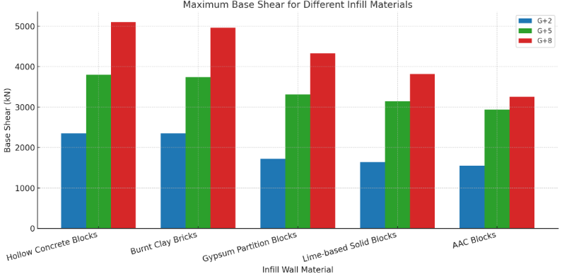
American Journal of Civil Engineering http://www.sciencepg.com/journal/ajce For all storey levels, hollow concrete blocks and brick infill section. systems demanded relatively larger beam sizes, with maxi- mum dimensions reaching 465 × 310 mm and 460 × 305 mm 4.2.2. Optimal Square Column Size Requirement respectively in the G+8 building. These infill materials have Table 8 outlines the minimum column dimensions needed higher stiffness and mass, thereby increasing the base shear for each infill wall material across the three building config- and bending moment demands on beams. urations. The interior column in ground floor (GF) is taken as Conversely, buildings modeled with AAC blocks required critical column since it is expected to take more load. Column the smallest beam sizes across all configurations, with min- sizes are expressed as square dimensions in millimeters. The imum sections of 300 × 200 mm for G+2 and 380 × 255 mm results indicate that column dimensions increase with the for G+8. This can be attributed to their lightweight and lower building height due to greater axial and lateral load accumu- stiffness, which reduce lateral force demands but also result in lation. higher structural flexibility, as discussed in the previous sub- Table 8. Minimum Square Column size obtained after analysis. Optimum column size (mm): S. N Infill- Wall material G+2 G+5 G+8 1 Hollow concrete blocks 340 490 610 2 Common brunt Clay Bricks 335 480 600 3 Gypsum partition block 315 455 570 4 Lime based solid blocks 310 450 560 5 AAC blocks 300 440 555 For each configuration, hollow concrete block infill re- sulted in the largest column sizes-up to 610 mm for G+8 4.3. Maximum Base Shear structures-attributed to the increased base shear and structural stiffness they induce. Similarly, brick masonry also required The magnitude of base shear depends significantly on the relatively large sections. In contrast, AAC block infill, being stiffness and mass of the structure, both of which are influ- lightweight and flexible, imposed lesser demands on column enced by the type of infill wall material used. Table 9 and dimensions, requiring a minimum of 300 mm in G+2 and 555 Figure 4 presents the maximum base shear values for build- mm in G+8. ings with different infill wall materials across G+2, G+5, and These results highlight the trade-off between stiffness and G+8 configurations. The data clearly indicate that buildings seismic demand: stiffer infill materials improve structural with hollow concrete block and brick infill experienced the rigidity but transfer greater forces to vertical load-bearing highest base shear values, with a peak of 5102.28 kN in the elements, necessitating more robust member sizes. Lighter G+8 configuration with hollow blocks. These materials are infill materials reduce this demand but may compromise on heavier and stiffer, increasing the effective mass and lateral lateral drift control and ductility unless compensated else- stiffness of the system, thereby attracting higher seismic where in the design. forces. Table 9. Maximum Base Shear for different Materials for G+2, G+5 and G+8. Base shear (kN) S. N Infill- Wall material G+2 G+5 G+8 1 Hollow concrete blocks 2350.55 3801.33 5102.28 2 Common brunt Clay Bricks 2349.31 3742.21 4962.30 252
Page 9
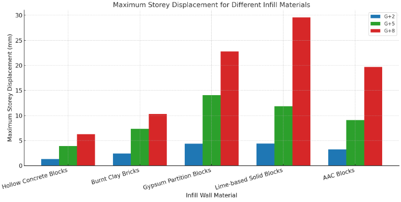
American Journal of Civil Engineering http://www.sciencepg.com/journal/ajce Base shear (kN) S. N Infill- Wall material G+2 G+5 G+8 3 Gypsum partition block 1723.30 3314.99 4326.32 4 Lime based solid blocks 1642.76 3142.68 3819.03 5 AAC blocks 1551.30 2937.34 3251.67 On the other hand, AAC blocks resulted in the lowest base behavior. Intermediate values were observed for gypsum shear, with values ranging from 1551.30 kN (G+2) to 3251.67 partition and lime-based blocks, which are lighter than tradi- kN (G+8), due to their lower density and relatively flexible tional masonry but offer moderate stiffness. Figure 4. Maximum base shear values for G+2, G+5, and G+8 storey RC framed buildings with different infill wall materials. These findings reaffirm the necessity of considering infill bility and its potential drift under lateral loads. The building wall characteristics during the design phase. Overlooking codes imposes limits on lateral displacements to ensure their impact could lead to either underestimation of base shear structural integrity and human safety during earthquakes. This for stiff infill materials or overdesign in the case of lighter study assessed the maximum storey displacements for G+2, partitions. G+5, and G+8 reinforced concrete framed buildings, modeled in ETABS, with various infill wall materials using the equiv- 4.4. Maximum Storey Displacement alent diagonal strut model. The maximum storey displace- ment was observed in top floor for all cases. The results are Maximum storey displacement reflects a structure’s flexi- summarized in Table 10 and visualized in Figure 5. Table 10. Maximum Storey displacement for different Materials for G+2, G+5 and G+8. Maximum Top Storey Displacement (mm) S. N Infill- Wall material G+2 G+5 G+8 1 Hollow concrete blocks 1.30 3.91 6.27 2 Common brunt Clay Bricks 2.41 7.33 10.29 253
Page 10
American Journal of Civil Engineering http://www.sciencepg.com/journal/ajce Maximum Top Storey Displacement (mm) S. N Infill- Wall material G+2 G+5 G+8 3 Gypsum partition block 4.39 14.07 22.78 4 Lime based solid blocks 4.41 11.85 29.57 5 AAC blocks 3.24 9.09 19.67 Hollow concrete block infill consistently produced the least Surprisingly, lime-based solid blocks, despite being denser displacement, owing to the high stiffness imparted by the than AAC, resulted in the highest displacement (29.57 mm) infill. In G+8 buildings, the displacement was limited to 6.27 for G+8. This may be due to a complex interaction of stiffness mm, showing its effectiveness in controlling lateral move- and mass contributing to dynamic amplification in taller ment. Burnt clay brick infill, although also stiff and dense, structures. showed slightly higher displacement values than hollow In taller structures (G+5 and G+8), the displacement dif- blocks, reaching 10.29 mm in G+8. Gypsum partition and ferences between infill types become more pronounced, em- AAC blocks, being more flexible and lightweight, led to sig- phasizing the importance of appropriate material selection for nificantly higher storey displacements. For example, gypsum seismic safety. Buildings with more deformable infill walls partition blocks caused a displacement of 22.78 mm in G+8 may require additional seismic bracing or shear walls to keep structures. displacements within code-prescribed limits. Figure 5. Maximum storey displacement for different number of floors with various materials in infill walls. be most demanding in the brick-infilled models and hollow concrete block models, whereas models with 5. Conclusion AAC and lime-based blocks required comparatively smaller cross-sectional dimensions. The study highlights the significant impact of infill mate- 3) Heavier infills results in the need for larger beam and rials on the seismic performance of RCC framed structures. column sizes to maintain structural safety, ultimately Some of the conclusion that can be drawn from this research increasing construction cost and material usage. are summarized below: 4) Time period analyses further confirm that heavier infills
- Conventional brick infill and hollow concrete blocks, result in stiffer but slower-responding structures, while while offering high stiffness and compressive strength, lighter infills provide higher flexibility and faster vibra- leads to increased seismic mass, which in turn elevates tion response, affecting dynamic behavior under seismic base shear forces and fundamental time periods. loads.
- Optimum beam-column size requirements were found to 254
Page 11
American Journal of Civil Engineering http://www.sciencepg.com/journal/ajce 5) Modern alternatives such as autoclaved aerated concrete 6) Life Cycle and Environmental Impact Analysis: Sus- (AAC) blocks, gypsum boards, and lime-based solid tainability considerations are increasingly critical in blocks demonstrate a reduction in seismic demand due material selection. Future research should perform life to their lower self-weight. Among these, AAC blocks cycle assessments (LCA) and cost-benefit analyses of notably reduce base shear and time period due to their various infill materials, comparing environmental im- lightweight nature but exhibit increased lateral dis- pacts, recyclability, carbon footprint, and long-term cost placement, requiring careful consideration in drift con- implications. trol. 6) Lime-based solid blocks emerge as a balanced solu- Abbreviations tion-offering moderate stiffness and weight, reduced displacement, and improved energy efficiency-without RC Reinforced Concrete substantially increasing structural member dimensions. AAC Autoclaved Aerated Concrete The overall analysis demonstrates that the lighter infill FEM Finite Element Method materials like AAC and gypsum reduce base shear, they may URM Unreinforced Masonry permit excessive lateral deformation. Conversely, denser MRF Moment Resisting Frame materials improve lateral stiffness but increase seismic de- GF Ground Floor mand. Therefore, in earthquake-prone regions like Nepal, IS Indian Standard where both seismic safety and cost-efficiency are vital, the infill wall material must be selected based on a balance be- tween displacement control and seismic force minimization. Conflicts of Interest The choice of infill material should be based on holistic as- sessment that includes seismic safety, displacement control, The authors declare no conflicts of interest. member sizing, energy efficiency and sustainability. References 6. Recommendation for Further Study [1] C. V. R. Murty, R. Goswami, A. R. Vijayanarayanan and V. V. While this study provides valuable insights into the influ- Mehta, “Some Concepts in Earthquake Behaviour of Buildings” Gujarat State Disaster Management Authority, Government of ence of various infill materials on seismic behavior of sym- Gujarat 001_30 May 2013”. metrical RC framed building, but still this is just a preliminary study considering general design procedures. Several areas [2] A. A. Costa, A. Penna, and G. Magenes, “Seismic performance warrant further exploration to deepen understanding and im- of Autoclaved Aerated Concrete (AAC) masonry: From ex- prove design practices. perimental testing of the in-plane capacity of walls to building
- Experimental Validation: Future research could include response simulation,” Journal of Earthquake Engineering, vol. 15, no. 1, pp. 1-31, Jan. 2011, experimental validation of the simulated results through https://doi.org/10.1080/13632461003642413 shake table tests or full-scale structural testing. This would help calibrate models and verify behavior under [3] P. Halder, S. Bhattacharjya, and S. Chakraborty, “Ener- real seismic excitations. The properties of various infill gy-Based Seismic Performance Assessment of Autoclaved materials can also be verified experimentally. Aerated Concrete Block-Infilled RC Building Structure,” 2025,
- Irregular Buildings: Further studies could examine how pp. 395-404. https://doi.org/10.1007/978-981-97-6067-1_38 different infill materials perform for buildings with ver- tically and stiffness irregularities. [4] B. M. Malagimani, S. B. Cholekar, and H. L. Sonawadekar,
- Seismic Performance Across Varying Intensities: Fur- “Comparative Study of RC Structures with Different Types of ther studies could examine how different infill materials Infill Walls with Effect of SSI by Pushover Analysis,” Inter- perform under varying seismic intensities and soil types. national Research Journal of Engineering and Technology,
- Infill-Frame Interaction and Nonlinear Behavior: The 2017, [Online]. Available: www.irjet.net complex interaction between infill panels and the [5] H. Varum, R. Dumaru, A. Furtado, A. R. Barbosa, D. Gautam, structural frame, especially under cyclic and post-elastic and H. Rodrigues, “Seismic performance of buildings in Nepal loading, needs more attention. Future studies should after the Gorkha earthquake,” in Impacts and Insights of the focus on the nonlinear in-plane and out-of-plane be- Gorkha Earthquake, Elsevier, 2018, pp. 47-63. havior of infills, as this interaction can significantly alter https://doi.org/10.1016/B978-0-12-812808-4.00003-1 the lateral load-resisting mechanism. [6] A. Wijeyewickrema, N. Subedi, and A. C. Wijeyewickrema,
- Fire and Acoustic Performance: Future studies should “Performance of RC Buildings with Masonry Infill Walls assess the fire resistance and sound insulation properties during the 2015 Gorkha, Nepal Earthquake.” [Online]. Avail- of modern infill materials, especially in high-density able: https://www.researchgate.net/publication/329887272 urban construction where these parameters are critical. 255
Page 12
American Journal of Civil Engineering http://www.sciencepg.com/journal/ajce [7] G. Zewdie Tsige, “Seismic Performance of Reinforced Con- [10] Bureau of Indian Standards, “IS 875-1 (1987): Code of Practice crete Buildings with Masonry Infill,” American Journal of For Design Loads (Other Than Earthquake) For Buildings And Civil Engineering, vol. 6, no. 1, p. 24, 2018, Structures, Part 1: Dead Loads - Unit Weights of Building https://doi.org/10.11648/j.ajce.20180601.15 Material And Stored Materials (Incorporating IS 1911 : 1967).” [8] “FEMA 356 Prestandard and Commentary for the Seismic [11] B. of Indian Standards, “IS 875 (Part 2): Code of Practice for Rehabilitation of Buildings,” 2000. Design Loads (Other Than Earthquake) For Buildings and Structures. Part 2: Imposed Loads (Second Revision),” 1989. [9] I. Standard, “la jpukvks a os Q Hkw dEijks /h fMtkbu os Q ekuna M Criteria for Earthquake Resistant Design of Structures [12] B. Panthi, P. Dahal, P. Shrestha, and K. B. Thapa, “Funda- Part 1 General Provisions and Buildings (Sixth Revision) mental period of RC buildings with infill walls in Nepal,” Hkkjrh; ekud,” 2016. [Online]. Available: www.standardsbis.in Asian Journal of Civil Engineering, vol. 22, no. 5, pp. 983-993, Jul. 2021, https://doi.org/10.1007/s42107-021-00359-y 256
American Journal of Civil Engineering, 2025, Vol. 13, No. 4