Page 1
Executive Summary This report presents the design and analysis of driven pile foundations of the proposed Peach Freeway Bridge over Turtle Creek. Due to the presence of scour potential and deep compressible soil layers, a deep foundation system consisting of 356 mm (14-inch) precast prestressed concrete driven piles was selected. Each substructure location supports a total axial compression load of 12,600 kN, with a maximum design load of 890 kN per single pile. A factor of safety of 2.0 is adopted for design. The objectives of this study include determination of required pile lengths at Pier 2 and Pier 3, verification of ultimate pile group capacity, evaluation of pile group settlement, and establishment of field driving criteria using dynamic formulas. Static capacity analyses were performed using both hand calculations and software-based methods. Settlement calculations were conducted using consolidation theory for cohesive soils. Driving criteria were established using the Modified Gates formula and the ENR formula. Final pile lengths, capacities, settlement values, and required blow counts will be presented following the analytical calculations.
- Project Background and Site Description The proposed bridge will span Turtle Creek and will consist of two abutments and two interior piers. The structure will have an approximate length of 80–100 meters. Due to hydraulic conditions and the potential for soil scouring, shallow foundations are not suitable, and a deep foundation system is required. Subsurface investigations indicate multiple soil layers, including stiff and very stiff silty clays. Laboratory consolidation testing provided the necessary parameters for settlement analysis, including pre consolidation pressure, initial void ratio, compression index, and recompression index. These parameters are essential for evaluating long-term consolidation settlement behavior.
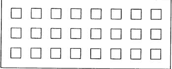
- Pile and Loading Information The selected foundation system consists of 356 mm precast prestressed concrete driven piles arranged in groups of 24 piles (three rows of eight piles) at each substructure location. The total axial compression load per substructure is 12,600 kN, and the maximum design load per pile is 890 kN. A factor of safety of 2.0 is used in static capacity design. Settlement requirements specify that total group settlement must not exceed 25 mm, and differential settlement between substructure units must not exceed 15 mm.
Page 2
Load Parameters: Factor of safety (FS)= 2 Compressive Load (Q )= 890 KN * FS = 890 KN * 2 = 1780 KN u Pile Geometry: Pile Type = Precast prestressed concrete (Square) Pile section = 0.356 mm x 0.356 mm Modulus of Elasticity (E) = 30 GPa Perimeter (p) = 1424 mm Tip Area (A) = 0.127 m2 3. Determination of Required Single Pile Length The single pile length was first estimated using APILE software (APPENDIX C) with the following parameters: Available Data: Table 1: Soil profile data at pier 2 (From S-2 boring log) Layer Soil Type Depth(m) Unit Weight N value (KN/m2) Top Bottom 1 Loose Silt 5 18 5 9 2 Extremely Dense 9 21.5 9 31 sand & Gravel 3 Dense Sand & Gravel 20 20 31 41 Note: All the soil layers are cohesionless. Since the water table is above the soil layers, the unit weight taken is the saturated unit weight APPENDIX C is the summary of capacity at each layer. Based on Table 2, when the minimum length is 8.6 meters, the capacity is larger than 1780 KN. Therefore, Ls for pier 2 is 8.6 meters. From APILE software, Parameter Value Design Requirement Check Ultimate Pile Capacity (Q_u) 1900 kN > Applied Load (1780kN) Safe Applied Load 1780 kN — —
Table 1 (Page 2)
| Layer | Soil Type | Depth(m) | Unit Weight (KN/m2) | N value | | | | --- | --- | --- | --- | --- | --- | --- | | | | | | Top | Bottom | | | 1 | Loose Silt | 5 | 18 | 5 | | 9 | | 2 | Extremely Dense sand & Gravel | 9 | 21.5 | 9 | | 31 | | 3 | Dense Sand & Gravel | 20 | 20 | 31 | | 41 |
Table 2 (Page 2)
| Parameter | Value | Design Requirement | Check | | --- | --- | --- | --- | | Ultimate Pile Capacity (Q_u) | 1900 kN | > Applied Load (1780kN) | Safe | | Applied Load | 1780 kN | — | — |
Page 3
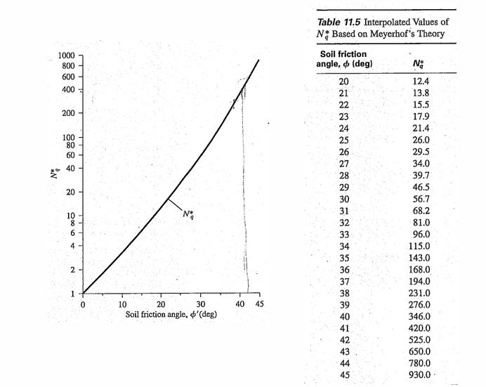
Settlement at 1780 kN 10 mm ≤ 25 mm OK The axial load carrying capacity of a single pile consists of shaft resistance (skin friction) and end bearing resistance at the pile tip. The ultimate capacity of a pile is expressed as: 𝑄 = 𝑄 +𝑄 𝑢 𝑠 𝑡 where Qu = ultimate capacity Qs = shaft resistance Qt = end bearing resistance For piles driven in cohesive soils, shaft resistance is calculated using the α-method: 𝑓 = α𝑐 𝑠 𝑢 For Cohesionless soil, 𝑓 = 2𝑁′ ≤ 100 kPa 𝑠 N’ = Average corrected SPT value The total shaft resistance is obtained by integrating the unit shaft resistance over the embedded surface area of the pile: 𝑄 = ∑(f ) 𝑠 s End bearing resistance in clay is calculated using: If the tip is in cohesive soil, 𝑄 = 𝑁 𝑐 𝐴 𝑡 𝑐 𝑢 𝑏 where N is typically taken as 9 for deep foundations in clay. c If the tip in cohesionless soil, (Meyerhof’s Method) 𝑄 = 𝐴 𝑞′𝑁∗ ≤ 𝐴 𝑝 𝑁∗tanϕ′ 𝑝 𝑝 𝑞 𝑝 𝑎 𝑞
Page 4
Figure 1:Soil Friction vs Nq* The allowable capacity is calculated as: 𝑄 𝑢 𝑄 = 𝑎𝑙𝑙𝑜𝑤 𝐹𝑆 The required pile length is determined by increasing embedment depth until the allowable capacity equals or exceeds the design load per pile. Static analyses were also performed using software tools, where soil properties, CPT data, and pile geometry were input to obtain ultimate capacities and recommended embedment lengths. The controlling pile length is selected based on meeting both strength and settlement requirements. 4. Ultimate Pile Group Capacity Pile group capacity is evaluated using two approaches: 4.1 Individual Pile Action If piles act independently and spacing is sufficient, the group capacity is: 𝑄 = 𝑛𝑄 𝑔𝑟𝑜𝑢𝑝 𝑠𝑖𝑛𝑔𝑙𝑒 where n is the number of piles. If the piles act dependently, typically when the pile is installed from 3 times diameter to 6 times diameter spacing. FWHA recommends that the pile spacing should not be less than
Page 5
3 times the pile diameter. The pile spacing it interpolated for the required spacing for the following data. η Center to Center Spacing 0.7 3D 1 6D And the pile group capacity is calculated. 𝑄 = η𝑛𝑄 𝑔𝑟𝑜𝑢𝑝 𝑠𝑖𝑛𝑔𝑙𝑒 4.2 Block Failure Mechanism When piles are closely spaced, the group may act as a single block. The block capacity consists of side resistance along the group perimeter and base resistance of the entire block: 𝑄 = 2𝐷(𝐵+𝑧)𝐶𝑢 +𝐵𝑧𝐶𝑢 𝑁 𝑢𝑔 1 2 𝑐 The ultimate group capacity is taken as the smaller of the individual pile sum and block capacity. The design requirement is satisfied when: 𝑄 𝑔𝑟𝑜𝑢𝑝 ≥ 12600 kN 𝐹𝑆 5. Settlement Analysis Pile group settlement in cohesive soils is primarily governed by consolidation theory. 5.1 Consolidation Settlement Primary consolidation settlement for normally consolidated clay is: 𝐶 𝐻 𝜎′ + Δ𝜎 𝑐 0 𝑆 = 𝑙𝑜𝑔( ) 1 + 𝑒 𝜎′ 0 0 For over consolidated clay, settlement is calculated using:
Table 1 (Page 5)
| η | Center to Center Spacing | | --- | --- | | 0.7 | 3D | | 1 | 6D |
Page 6
𝐶 𝐻 𝑃 𝐶 𝐻 σ′ +Δσ 𝑐𝑟 𝑐 𝑐 0 𝑆 = log( )+ log( ) 1+𝑒 σ′ 1+𝑒 𝑃 0 0 0 𝑐 Total settlement is the sum of settlement contributions from all compressible layers. The design is acceptable if total settlement does not exceed 25 mm and differential settlement remains below 15 mm. For cohesionless soil, (Meyerhof, 1976) 42 𝑝 𝐵 𝐼 𝑓 𝑓 𝑠 = 𝑞 𝑐 Where, p = Design Foundation Pressure (kPa) f B = Width of the Pile Group (m) I = Influence Factor = 1- [D / 8B] ≥ 0.5 f q = Average Cone Tip Resistance c 6. Pile Driving Analysis Dynamic pile driving formulas relate hammer energy to pile resistance and are used to establish field driving criteria. 6.1 Engineering News Record (ENR) Formula e 𝐸 ℎ 𝑄 = 𝑢 𝑆+𝐶 where E = hammer energy S = penetration per blow C = empirical constant e = hammer efficiency h The allowable capacity is: 𝑄 𝑢 𝑄 = 𝑎𝑙𝑙𝑜𝑤 𝐹𝑆 Blow count requirements are determined by solving penetration corresponding to the required design load. 6.2 Modified Gates Formula
Page 7
The Modified Gates formula relates allowable capacity to blow count: 1.25 𝑒 𝐸 𝑊 +𝑛2𝑊 ℎ ℎ 𝑟 𝑝 𝑄 = ⋅ 𝑢 𝑠+𝐶 𝑊 +𝑊 𝑟 𝑝 7. Calculation of Load Bearing Capacity and Pile Driving Analysis 7.1 Pier 2 (L = 8.6m) (APPENDIX A) From APILE we got the initial length of pile foundation to be 8.6 meters, the calculations and checks were done for the given pile (APPENDIX A). The summary of the calculations are as follows: Value Value Category Parameter Requirement Check (kips) (kN) Single Pile Ultimate Capacity 440 1,960 — — (Static – SPT) (Q_u) Allowable (FS = 2) 220 980 ≥ 890 kN OK Single Pile Allowable 267 1,190 ≥ 890 kN OK (ENR) Approx. Ultimate (FS 1,600 7,120 — — removed) Single Pile (Modified Nominal/Ultimate 705 3,140 — — Gates) Pile Group (24 Ultimate (Sum of 10,560 47,000 ≥ 25,200 kN OK piles) piles) Required Ultimate (2 5,660 25,200 — — × 12,600) Sum of No Governing Mode piles — — block controls failure Settlement Estimated — 3 mm ≤ 25 mm OK (Service Load) Settlement
Table 1 (Page 7)
| Category | Parameter | Value (kips) | Value (kN) | Requirement | Check | | --- | --- | --- | --- | --- | --- | | Single Pile (Static – SPT) | Ultimate Capacity (Q_u) | 440 | 1,960 | — | — | | | Allowable (FS = 2) | 220 | 980 | ≥ 890 kN | OK | | Single Pile (ENR) | Allowable | 267 | 1,190 | ≥ 890 kN | OK | | | Approx. Ultimate (FS removed) | 1,600 | 7,120 | — | — | | Single Pile (Modified Gates) | Nominal/Ultimate | 705 | 3,140 | — | — | | Pile Group (24 piles) | Ultimate (Sum of piles) | 10,560 | 47,000 | ≥ 25,200 kN | OK | | | Required Ultimate (2 × 12,600) | 5,660 | 25,200 | — | — | | | Governing Mode | Sum of piles controls | — | — | No block failure | | Settlement (Service Load) | Estimated Settlement | — | 3 mm | ≤ 25 mm | OK |
Page 8
Comparing hand calculated and software data: Qu = 1900 kN from APILE, 1960 kN from hand calculation Settlement = 3mm from hand calculation and 5 mm from APILE This gives sufficient evidence to verify our output from both methods. 7.2 Pier 3 (L = 19m) (APPENDIX B) From Cone Pine Analysis software, the length of pile that can sustain the load was 13.6 m, but this length resulted in the raft depth in the clayey layer, which made the settlement of the pile foundation very high ( >>25mm). So, we took the length of the pile as 19 m, making the raft depth in the Dense, Sand and Gravel layer. Category Parameter Value Value Requirement Check (kips) (kN) Single Pile Ultimate Capacity 762 3,390 — — (Static – SPT, L (Qu) = 19 m) Allowable (FS = 2) 381 1,695 ≥ 890 kN OK Single Pile Allowable 267 1,190 ≥ 890 kN OK (ENR) Approx. Ultimate (FS 1,600 7,120 — — removed) Single Pile Nominal/Ultimate 705 3,140 — — (Modified Gates) Pile Group (24 Ultimate (Sum of 18,277 81,300 ≥ 25,200 kN OK piles) piles) Required Ultimate 5,665 25,200 — — (2 × 12,600) Governing Mode Sum of — — No piles block controls failure
Table 1 (Page 8)
| Category | Parameter | Value (kips) | Value (kN) | Requirement | Check | | --- | --- | --- | --- | --- | --- | | Single Pile (Static – SPT, L = 19 m) | Ultimate Capacity (Qu) | 762 | 3,390 | — | — | | | Allowable (FS = 2) | 381 | 1,695 | ≥ 890 kN | OK | | Single Pile (ENR) | Allowable | 267 | 1,190 | ≥ 890 kN | OK | | | Approx. Ultimate (FS removed) | 1,600 | 7,120 | — | — | | Single Pile (Modified Gates) | Nominal/Ultimate | 705 | 3,140 | — | — | | Pile Group (24 piles) | Ultimate (Sum of piles) | 18,277 | 81,300 | ≥ 25,200 kN | OK | | | Required Ultimate (2 × 12,600) | 5,665 | 25,200 | — | — | | | Governing Mode | Sum of piles controls | — | — | No block failure |
Page 9
Settlement Estimated — 18 mm ≤ 25 mm OK (Service Load) Settlement From Cone Pile Analysis, at depth of 19 m the total pile capacity was 7. Discussion The pile lengths determined through static analysis ensure that both strength and settlement criteria are satisfied. Comparison between individual pile capacity and block failure mechanisms provides insight into group interaction effects. Settlement results confirm compliance with allowable limits. Driving criteria derived from dynamic formulas ensure that the required design capacity can be verified during construction. 8. Conclusions The driven pile foundation system satisfies structural capacity, settlement, and constructability requirements. Required pile lengths at Pier 2 and Pier 3 will be finalized following calculations. Ultimate group capacity exceeds required design load when the factor of safety is applied. Predicted settlement remains within allowable limits. Driving criteria have been established to guide field installation. For both pier, the pile foundation with the configuration given below can be used with center-to-center spacing of 1.25m 1.25m For Pier 2, Length of 8.6 m will be sufficient to satisfy all the structural requirements. For Pier 3, length of 19 m will be sufficient.
Page 10
- References American Association of State Highway and Transportation Officials (AASHTO). (2020). AASHTO LRFD bridge design specifications (9th ed.). Washington, DC: AASHTO. Bowles, J. E. (1996). Foundation analysis and design (5th ed.). New York, NY: McGraw-Hill. Das, B. M., & Sobhan, K. (2018). Principles of foundation engineering (9th ed.). Boston, MA: Cengage Learning. FHWA. (2016). Design and construction of driven pile foundations (FHWA-NHI-16-009). Federal Highway Administration, U.S. Department of Transportation. Meyerhof, G. G. (1976). Bearing capacity and settlement of pile foundations. Journal of the Geotechnical Engineering Division, 102(GT3), 195–228. NAVFAC. (1986). Soil mechanics, foundations, and earth structures (DM 7.02). Naval Facilities Engineering Command. Terzaghi, K., Peck, R. B., & Mesri, G. (1996). Soil mechanics in engineering practice (3rd ed.). New York, NY: Wiley. Tomlinson, M. J., & Woodward, J. (2015). Pile design and construction practice (6th ed.). Boca Raton, FL: CRC Press. Vesic, A. S. (1977). Design of pile foundations. National Cooperative Highway Research Program Synthesis of Highway Practice, 42.
Page 11
APPENDIX A : Calculations for Pier 2 (Taking Length of Pile = 8.6m from APENDIX C) Single pile shaft capacity 𝑄 𝑠 Segment A: 0–5 m (loose silt) Take an average 𝑁in this zone from SS-1 to SS-4: 8+11+11+14 𝑁 ≈ = 11 𝑎𝑣𝑔 4 𝑓 = 2𝑁 = 22 kPa 𝑠 𝑄 = 𝑓 𝑃 𝐿 = 22(1.424)(5) = 156.6 kN 𝑠1 𝑠 Segment B: 5–8 m (extremely dense sand & gravel) Here 𝑁is huge ⇒ 2𝑁 > 100so we use the cap: 𝑓 = 100 kPa 𝑠 𝑄 = 100(1.424)(3) = 427.2 kN 𝑠2 Segment C: 8–8.6 m (dense sand & gravel) At SS-7, 𝑁 = 49 ⇒ 𝑓 = 2𝑁 = 98 kPa(below cap) 𝑠 𝑄 = 98(1.424)(0.6) = 83.7 kN 𝑠3 Total shaft resistance 𝑄 = 156.6+427.2+83.7 = 667.5 kN 𝑠 Single pile tip capacity 𝑄 𝑝 𝑄 = 𝐴 𝑞′ 𝑁* ≤ 𝐴 𝑝 𝑁* tan𝜙′ 𝑝 𝑝 𝑞 𝑝 𝑎 𝑞 • Take 𝑝 = 100 kPa. 𝑎 • Bearing factor (standard): 𝑁 (𝜙′ = 45∘) ≈ 134 𝑞 o 0–5 m silt: 𝛾′ ≈ 8 kN/m3 o 5–8.6 m sand/gravel: 𝛾′ ≈ 10 kN/m3 Then:
Page 12
𝑞′ = (8)(5)+(10)(3.6) = 40+36 = 76 kPa (1) Overburden expression 𝑄 = 𝐴 𝑞′𝑁 = 0.1267(76)(134) = 1291 kN 𝑝1 𝑝 𝑞 (2) Limiting expression 𝑄 = 𝐴 𝑝 𝑁 tan𝜙′ = 0.1267(100)(134)(tan45∘) = 0.1267(13400) = 1698 kN 𝑝2 𝑝 𝑎 𝑞 So the governing is the smaller: 𝑄 = 1291 kN 𝑝 5) Single pile ultimate capacity 𝑄 = 𝑄 +𝑄 = 667.5+1291 = 1958.5 kN 𝑢 𝑠 𝑝 With FS = 2.0: 𝑄 = 𝑄𝑢 = 979 kN> 890 kN(safe) 𝑎𝑙𝑙𝑜𝑤 2 Ultimate pile group capacity (24 piles, spacing = 1.5 m c/c) Sum of individual pile capacities (with group efficiency) Pile spacing ratio: 𝑠 1.5 = = 4.21 > 3 𝐵 0.356 For driven piles in sand/gravel at spacing > ~3B, taking group efficiency 𝜂 ≈ 1.0. 𝑄 = 𝜂 𝑛 𝑄 = (1.0)(24)(1958.5) = 47004 kN 𝑢,𝑔𝑟𝑜𝑢𝑝 𝑢 Required ultimate group capacity (FS = 2 on the 12,600 kN load): 𝑄 = 2(12600) = 25200 kN (safe) 𝑟𝑒𝑞,𝑢𝑙𝑡 Block failure check Group layout: 3 rows × 8 piles, spacing 𝑠 = 1.5m, pile width 𝐵 = 0.356m.
Page 13
Block plan dimensions: 𝐿 = (8−1)𝑠+𝐵 = 7(1.5)+0.356 = 10.856 m 𝑊 = (3−1)𝑠+𝐵 = 2(1.5)+0.356 = 3.356 m 𝐴 = 𝐿𝑊 = 10.856(3.356) = 36.43 m2 𝑏𝑙𝑜𝑐𝑘 𝑃 = 2(𝐿+𝑊) = 2(10.856+3.356) = 28.424 m 𝑏𝑙𝑜𝑐𝑘 Block side resistance • 0–5 m: 𝑓 = 22 kPa 𝑠 𝑄 = 22(28.424)(5) = 3127 kN 𝑠,𝑏𝑙𝑜𝑐𝑘1 • 5–8 m: 𝑓 = 100 kPa 𝑠 𝑄 = 100(28.424)(3) = 8527 kN 𝑠,𝑏𝑙𝑜𝑐𝑘2 • 8–8.6 m: 𝑓 ≈ 100 kPa 𝑠 𝑄 = 100(28.424)(0.6) = 1705 kN 𝑠,𝑏𝑙𝑜𝑐𝑘3 𝑄 = 3127+8527+1705 = 13359 kN 𝑠,𝑏𝑙𝑜𝑐𝑘 Block base resistance Using the same governing base stress at tip: 𝑞 = 𝑞′𝑁 = 76(134) = 10184 kPa 𝑏 𝑞 𝑄 = 𝐴 𝑞 = 36.43(10184) = 371003 kN 𝑝,𝑏𝑙𝑜𝑐𝑘 𝑏𝑙𝑜𝑐𝑘 𝑏 So: 𝑄 = 𝑄 +𝑄 ≈ 384362 kN 𝑢,𝑏𝑙𝑜𝑐𝑘 𝑠,𝑏𝑙𝑜𝑐𝑘 𝑝,𝑏𝑙𝑜𝑐𝑘 Governing group ultimate capacity (𝑠𝑢𝑚) 𝑄 = min(𝑄 ,𝑄 ) = 47004 kN 𝑢,𝑔𝑟𝑜𝑢𝑝 𝑢,𝑔𝑟𝑜𝑢𝑝 𝑢,𝑏𝑙𝑜𝑐𝑘 Block failure does NOT control (block capacity is far larger). Settlement calculation
Page 14
Equivalent raft depth (standard assumption for pile groups) 2 𝑧 ≈ 𝐿 𝑟 3 𝑝𝑖𝑙𝑒 Pile length used: 𝐿 = 8.6 m ⇒ 𝑧 = 5.73 m 𝑝𝑖𝑙𝑒 𝑟 At ~5.7 m depth in Boring S-2, soil is extremely dense sand & gravel (SPT N is extremely high there), so settlement is mainly immediate elastic compression, not consolidation. Soil stiffness from SPT N (Boring S-2) From S-2 around 5–8 m: 𝑁 ≈ 131to 151. Take average: 𝑁 ≈ 140 𝑎𝑣𝑔 𝐸 ≈ 2.5𝑁 (MPa) 𝑠 𝐸 ≈ 2.5(140) = 350 MPa = 350,000 kPa 𝑠 Assume Poisson’s ratio for sand/gravel: 𝜈 ≈ 0.30 Immediate settlement of equivalent raft Use the elastic settlement form: 𝑞 𝐵 (1−𝜈2) 𝐼 𝑒 𝑠 = 𝐸 𝑠 Take 𝐵 as the smaller raft dimension: 𝑒 𝐵 = 𝑊 = 3.356 m 𝑒 For a rectangular footing, I = 1.0 With 𝐼 = 1.0 (346)(3.356)(1−0.32)(1.0) 𝑠 = 350000 1−0.32 = 0.91
Page 15
346×3.356×0.91 1056.7 𝑠 = = = 0.00302 m = 3.0 m 350000 350000 Pile Driving Analysis Assumed driving data (typical for 14-in prestressed pile) • Hammer type: diesel / impact hammer • Ram weight: 𝑊 = 5,000 lb = 2.5 tons 𝑅 • Stroke at end of drive (EOD): ℎ = 8 ft • Penetration per blow : 20 blows/in 1 𝑠 = = 0.05 in/blow 20 • ENR constant: 𝑐 = 0.1 in(standard) • Developed hammer energy for Gates: 𝐸 = 𝑊 ℎ = (5,000 lb)(8 ft) = 40,000 ft-lb 𝑅
- ENR formula (gives allowable resistance; FS≈6 ) 𝑊 ℎ 𝑅 𝑄 = 𝑠+𝑐 (with 𝑐 = 0.1 inwhen 𝑠is in inches) Use W in tons, h in ft, s and c in inches → result is in tons: (2.5)(8) 20 𝑄 = = = 133.3 tons 𝐸𝑁𝑅 0.05+0.1 0.15 Convert to kips: 133.3 tons×2 = 266.7 kips Convert to kN: 266.7 kips×4.448 = 1186 kN ENR (allowable) capacity
Page 16
𝑄 ≈ 267 kips ≈ 1,190 kN 𝑎𝑙𝑙𝑜𝑤,𝐸𝑁𝑅 𝑄 ≈ 6(266.7) = 1600 kips ≈ 7115 kN 𝑢,𝐸𝑁𝑅 2) FHWA-Modified Gates formula FHWA-modified Gates: 𝑅 = 1.75√𝐸 *log (10𝑁)−100 𝑛 10 where: • 𝑅 = nominal (ultimate) pile resistance in kips 𝑛 • 𝐸= developed hammer energy in ft-lb • 𝑁= blows per inch (blows/in) Plug in: • 𝐸 = 40,000 ft-lb ⇒ √𝐸 = 200 • 𝑁 = 20 ⇒ log (10𝑁) = log (200) = 2.301 10 10 𝑅 = 1.75(200)(2.301)−100 = 805.35−100 = 705.35 kips 𝑛 Convert to kN: 705.35×4.448 = 3137 kN Modified Gates ultimate / nominal capacity 𝑄 = 3,140 kN 𝑢,Gates Q = 3140/3 =1047 kN u,allowable
Page 17
APPENDIX B : Calculations for pier 3 (Taking Length = 19 m from APPENDIX D) For values less than 19m, the raft depth falls on the clayey layers, which makes the settlement very high. Pile (14 in square): 𝐵 = 0.356 m 𝐴 = 0.3562 = 0.1267 m2,𝑃 = 4(0.356) = 1.424 m 𝑝 Group (24 piles, 3×8, 𝑠 = 1.5m): 𝐿 = 10.856 m,𝑊 = 3.356 m 𝑔 𝑔 𝐴 = 36.43 m2,𝑃 = 28.424 m 𝑔 𝑔 Pier load 𝑄 = 12,600 kN: 12600 𝑞 = = 346 kPa 36.43
- Single pile ultimate capacity (L = 19 m) 1.1 Shaft resistance (fs = 100kPa control the shaft resistance) 𝑓 = 100 kPa 𝑠 𝑄 = 𝑓𝑃𝐿 = 100(1.424)(19) = 2706 kN 𝑠 𝑠 𝑄 ≈ 2,710 kN 𝑠 1.2 Tip resistance (tip in dense sand & gravel) Use: 𝑄 = 𝐴 𝑞′𝑁\* ≤ 𝐴 𝑝 𝑁\tan𝜙′ 𝑝 𝑝 𝑞 𝑝 𝑎 𝑞 Assume dense sand/gravel: 𝜙′ = 40∘, 𝑁\ = 64, 𝑝 = 100 kPa, 𝛾′ ≈ 10 kN/m 3 𝑞 𝑎 𝑞′ = 𝛾′𝑧 = 10(19) = 190 kPa Overburden form: 𝑄 = 0.1267(190)(64) = 1541 kN 𝑝1
Page 18
Limit form: 𝑄 = 0.1267(100)(64)tan40∘ = 681 kN 𝑝2 Governing: 𝑄 ≈ 681 kN 𝑝 1.3 Single pile ultimate 𝑄 = 𝑄 +𝑄 = 2706+681 = 3387 kN 𝑢 𝑠 𝑝 𝑄 ≈ 3,390 kN 𝑢,single 2) Group ultimate capacity (24 piles) + block failure 2.1 Group ultimate (sum; 𝑠/𝐵 = 4.21 > 3 ⇒ 𝜂 ≈ 1) 𝑄 = 24(3387) = 81,288 kN 𝑢,group(sum) 𝑄 ≈ 81,300 kN 𝑢,group Required ultimate (FS=2 on 12,600 kN): 𝑄 = 25,200 kN > 12600kN (ok) 𝑟𝑒𝑞,𝑢𝑙𝑡 2.2 Block failure check Side resistance: 𝑄 = 100(28.424)(19) = 53,986 kN 𝑠,block Base stress: 𝑞 = 𝑞′𝑁 = 190(64) = 12,160 kPa 𝑏 𝑞 𝑄 = 𝐴 𝑞 = 36.43(12,160) = 442,990 kN 𝑝,block 𝑔 𝑏 𝑄 ≈ 496,976 kN 𝑢,block Block ≫sum → block failure does not govern. 3) Settlement (L = 19 m) Equivalent raft depth:
Page 19
2 2 𝑧 = 𝐿 = (19) = 12.67 m 𝑟 3 3 Dense sand starts at 13.0 m ⇒ compressible clay below raft: 𝐻 = 13.0−12.67 = 0.33 m So only 0.33 m of Layer 2 clay remains below the raft (very small). Use Layer 2 props: 𝑃 = 200 kPa, 𝑒 = 0.80, 𝐶 = 0.30, 𝐶 = 0.03 𝑐 0 𝑐 𝑐𝑟 Stress increase at mid-depth below raft (2:1), take 𝑧 = 𝐻/2 = 0.165m: 36.43 Δ𝜎 = 346 ≈ 328 kPa (10.856+0.165)(3.356+0.165) Initial effective stress at depth 12.67+0.165 = 12.83m (using 𝛾′ ≈ 10): 𝜎′ ≈ 128 kPa 0 𝜎′ ≈ 128+328 = 456 kPa 𝑓 Settlement: 𝐶 𝐻 𝑃 𝐶 𝐻 𝜎′ 𝑐𝑟 𝑐 𝑐 𝑓 𝑆 = log ( )+ log ( ) 1+𝑒 10 𝜎′ 1+𝑒 10 𝑃 0 0 0 𝑐 Computing (with 𝐻 = 0.33m): 𝑆 ≈ 0.018 m = 18 mm 𝑆 ≈ 0.018 m (18 mm) ≤ 25𝑚𝑚(𝑆𝑎𝑓𝑒) 𝑝𝑖𝑒𝑟3 ENR formula (using assumed driving data) Assume: 𝑊 = 5000 lb = 2.5 tons, ℎ = 8 ft 𝑅 1 EOD blows/in: 𝑁 = 20 ⇒ 𝑠 = = 0.05 in/blow 𝑁 ENR constant: 𝑐 = 0.10 in
Page 20
𝑊 ℎ 𝑅 𝑄 = 𝐸𝑁𝑅 𝑠+𝑐 (use 𝑊 in tons, ℎin ft, 𝑠,𝑐in inches → 𝑄in tons) 𝑅 (2.5)(8) 20 𝑄 = = = 133.33 tons 𝐸𝑁𝑅 0.05+0.10 0.15 Convert: 133.33 tons×2 = 266.67 kips 266.67 kips×4.448 = 1186 kN Modified Gates formula (FHWA form, nominal/ultimate) Assume: Developed energy 𝐸 = 𝑊 ℎ = (5000)(8) = 40,000 ft-lb 𝑅 Blows/in 𝑁 = 20 𝑅 = 1.75√𝐸 log (10𝑁)−100(kips) 𝑛 10 √𝐸 = √40,000 = 200 log (10𝑁) = log (200) = 2.301 10 10 𝑅 = 1.75(200)(2.301)−100 = 805.35−100 = 705.35 kips 𝑛 705.35 kips×4.448 = 3137 kN
Page 21
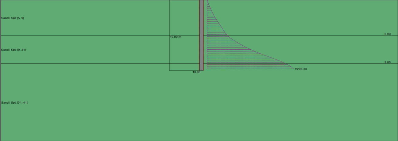
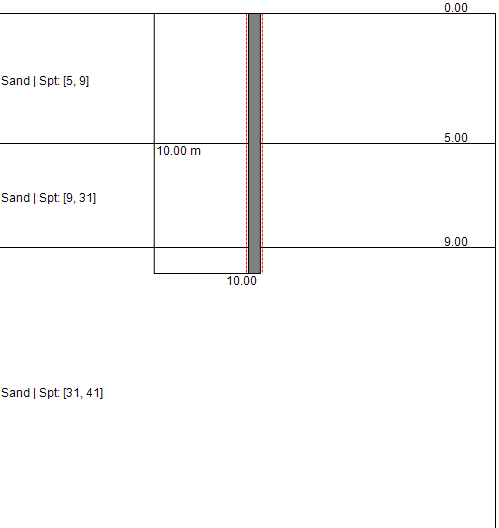
APPENDIX C : Software Input and Output for Pier 2 Pier 2 Figure 2 - Pile Model
Page 22
Table 1 - FED. HWY. METHOD PILE LENGTH BELOW SKIN FRICTION KN. END BEARING KN. ULTIMATE CAPACITY GND. M. KN. 0.00 0.0 10.6 10.6 0.30 0.8 22.3 23.2 0.61 3.3 38.4 41.7 0.91 7.4 57.6 65.1 1.22 13.2 77.2 90.4 1.52 20.7 96.9 117.6 1.83 29.9 116.8 146.7 2.13 40.7 137.0 177.7 2.44 53.2 157.3 210.5 2.74 67.5 177.8 245.3 3.05 83.5 198.5 281.9 3.35 101.2 219.3 320.5 3.66 120.6 239.0 359.6 3.96 141.7 255.5 397.2 4.27 164.7 267.9 432.6 4.57 189.3 279.7 469.0 4.88 215.8 301.2 517.0 5.18 244.0 329.6 573.6 5.49 275.1 370.5 645.6 5.79 309.8 424.8 734.6 6.10 347.8 480.7 828.5 6.40 389.4 541.3 930.6 6.71 434.5 606.9 1041.5 7.01 483.5 676.9 1160.4 7.32 536.8 750.9 1287.7
Table 1 (Page 22)
| | PILE LENGTH BELOW | SKIN FRICTION KN. | END BEARING KN. | | ULTIMATE CAPACITY | | --- | --- | --- | --- | --- | --- | | | GND. M. | | | | KN. | | 0.00 | | 0.0 | 10.6 | 10.6 | | | 0.30 | | 0.8 | 22.3 | 23.2 | | | 0.61 | | 3.3 | 38.4 | 41.7 | | | 0.91 | | 7.4 | 57.6 | 65.1 | | | 1.22 | | 13.2 | 77.2 | 90.4 | | | 1.52 | | 20.7 | 96.9 | 117.6 | | | 1.83 | | 29.9 | 116.8 | 146.7 | | | 2.13 | | 40.7 | 137.0 | 177.7 | | | 2.44 | | 53.2 | 157.3 | 210.5 | | | 2.74 | | 67.5 | 177.8 | 245.3 | | | 3.05 | | 83.5 | 198.5 | 281.9 | | | 3.35 | | 101.2 | 219.3 | 320.5 | | | 3.66 | | 120.6 | 239.0 | 359.6 | | | 3.96 | | 141.7 | 255.5 | 397.2 | | | 4.27 | | 164.7 | 267.9 | 432.6 | | | 4.57 | | 189.3 | 279.7 | 469.0 | | | 4.88 | | 215.8 | 301.2 | 517.0 | | | 5.18 | | 244.0 | 329.6 | 573.6 | | | 5.49 | | 275.1 | 370.5 | 645.6 | | | 5.79 | | 309.8 | 424.8 | 734.6 | | | 6.10 | | 347.8 | 480.7 | 828.5 | | | 6.40 | | 389.4 | 541.3 | 930.6 | | | 6.71 | | 434.5 | 606.9 | 1041.5 | | | 7.01 | | 483.5 | 676.9 | 1160.4 | | | 7.32 | | 536.8 | 750.9 | 1287.7 | |
Page 23
7.62 595.2 829.6 1424.9 7.92 659.4 913.9 1573.2 8.23 729.4 1001.3 1730.8 8.53 805.8 1078.5 1884.2 8.84 888.6 1131.9 2020.5 9.14 977.5 1158.5 2136.0 9.45 1070.0 1155.6 2225.6 9.75 1164.6 1131.7 2296.3 Table 2 is the summary of capacity at each layer. Based on Table 2, when the minimum length is 8.6 meters, the capacity is larger than 1780 KN. Therefore, Ls for pier 2 is 8.6 meters. Axial Capacity (kN) 0 500 1000 1500 2000 2500 0 2 4 )m Skin Friction ( n o Tip Resistance it a r t 6 Total Capacity e n e P e liP 8 10 12
Table 1 (Page 23)
| 7.62 | 595.2 | 829.6 | 1424.9 | | --- | --- | --- | --- | | 7.92 | 659.4 | 913.9 | 1573.2 | | 8.23 | 729.4 | 1001.3 | 1730.8 | | 8.53 | 805.8 | 1078.5 | 1884.2 | | 8.84 | 888.6 | 1131.9 | 2020.5 | | 9.14 | 977.5 | 1158.5 | 2136.0 | | 9.45 | 1070.0 | 1155.6 | 2225.6 | | 9.75 | 1164.6 | 1131.7 | 2296.3 |
Page 24
FHWA Axial Load (kN) 0 500 1000 1500 2000 2500 0.00E+00 1.00E-02 )m 2.00E-02 ( t FHWA n e m 3.00E-02 e lt t e 4.00E-02 S 5.00E-02 6.00E-02
Page 25
APPENDIX D : Software Input and Output for Pier 3
Foundation Engineering project