Slide 1
Effect of Dome Geometry on Stress Distribution in Propane Tanks
Presented By: Sabin Khatri and Deepak Yadav
Instructor: Dr. David Edward Hall
Slide 2
INTRODUCTION
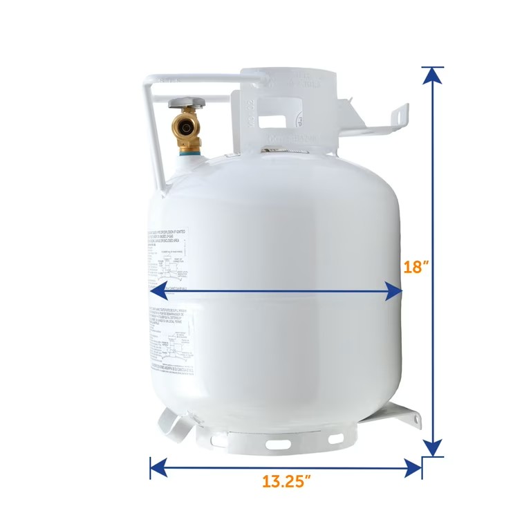
Propane tanks are pressure vessels used to safely store gas under internal pressure.
In this project, three dome shapes were compared:
1.Parabolic dome 2.Circular dome 3.Flat dome
The goal of this project was to understand how dome geometry affects stress distribution in a propane tank.
Simulation conditions:
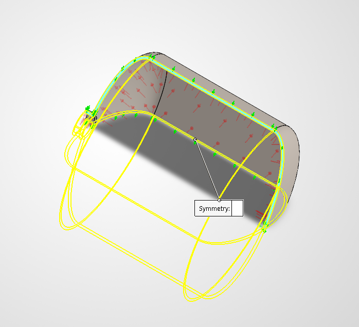
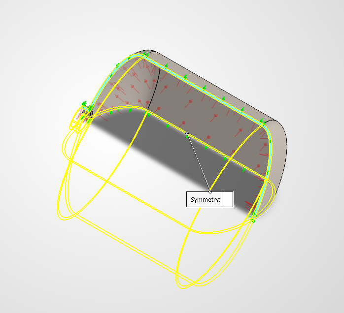
1/4 symmetry model used for each tank design Internal pressure applied: 250 psi Thickness of tank: 0.2 inch Stress results compared: axial stress, hoop stress, and von Mises stress
Slide 3
Parabolic Dome
Slide 4
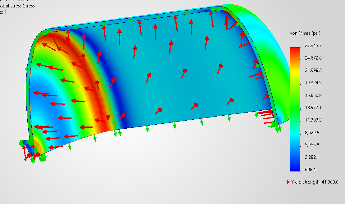
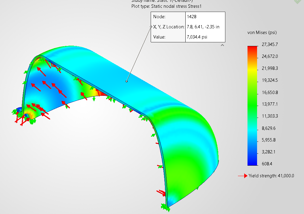
Maximum Von Mises Stress of 27345.7psi at the interface between the cylindrical and parabolic dome.
This region has a change in geometry and curvature.
The stress path changes at the dome-to-cylinder connection.
The cylindrical section and dome carry pressure differently. This causes combined hoop, axial, and bending stresses.
As a result, stress becomes concentrated at the transition area. Therefore, high von Mises stress at this interface is expected and reasonable.
Slide 5
Axial Stress at the cylindrical portion
Hoop Stress at Cylindrical Portion
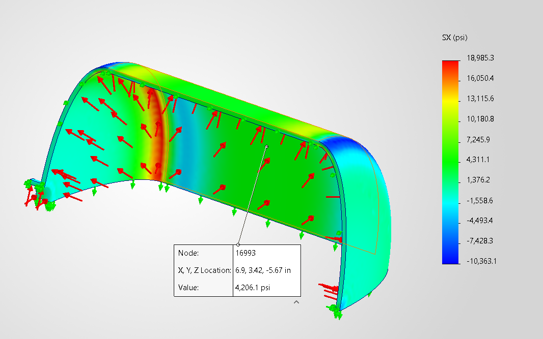
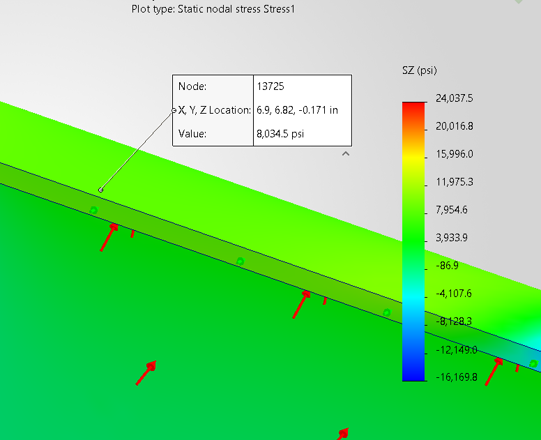
Table (Slide 5)
| Stress Type | Analytical Stress (psi) | SolidWorks Stress (psi) | Difference (psi) | Percent Difference | | --- | --- | --- | --- | --- | | Hoop Stress | 8,287.5 | 8,034.5 | 253.0 | 3.05% | | Axial Stress | 4,143.75 | 4,206.1 | 62.35 | 1.50% |
The hoop stress difference is about 3.05%, which is still very small. This shows that the SolidWorks hoop stress result matches well with the analytical thin-wall pressure vessel equation. The axial stress difference is only about 1.50%, so the SolidWorks axial stress also agrees very closely with the analytical result.
Slide 6
Circular Dome
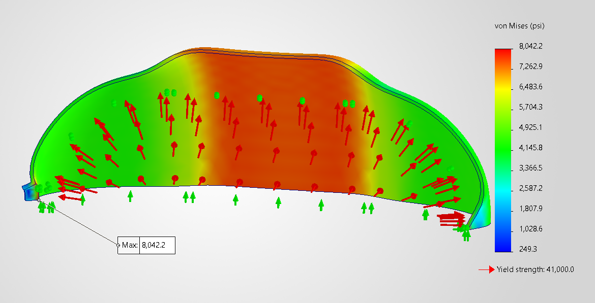
Maximum von Mises stress is 8,042.2 psi, much lower than the parabolic dome.
Curved geometry spreads internal pressure more evenly.
Higher stress appears across the central curved region.
Lower stress appears near the sides and supports.
Some stress concentration still occurs at the dome-to-cylinder interface.
Compared to the parabolic dome, the circular dome has more uniform curvature, so stress spreads more broadly.
Overall, the circular dome carries pressure more efficiently than the flat dome.
Slide 7
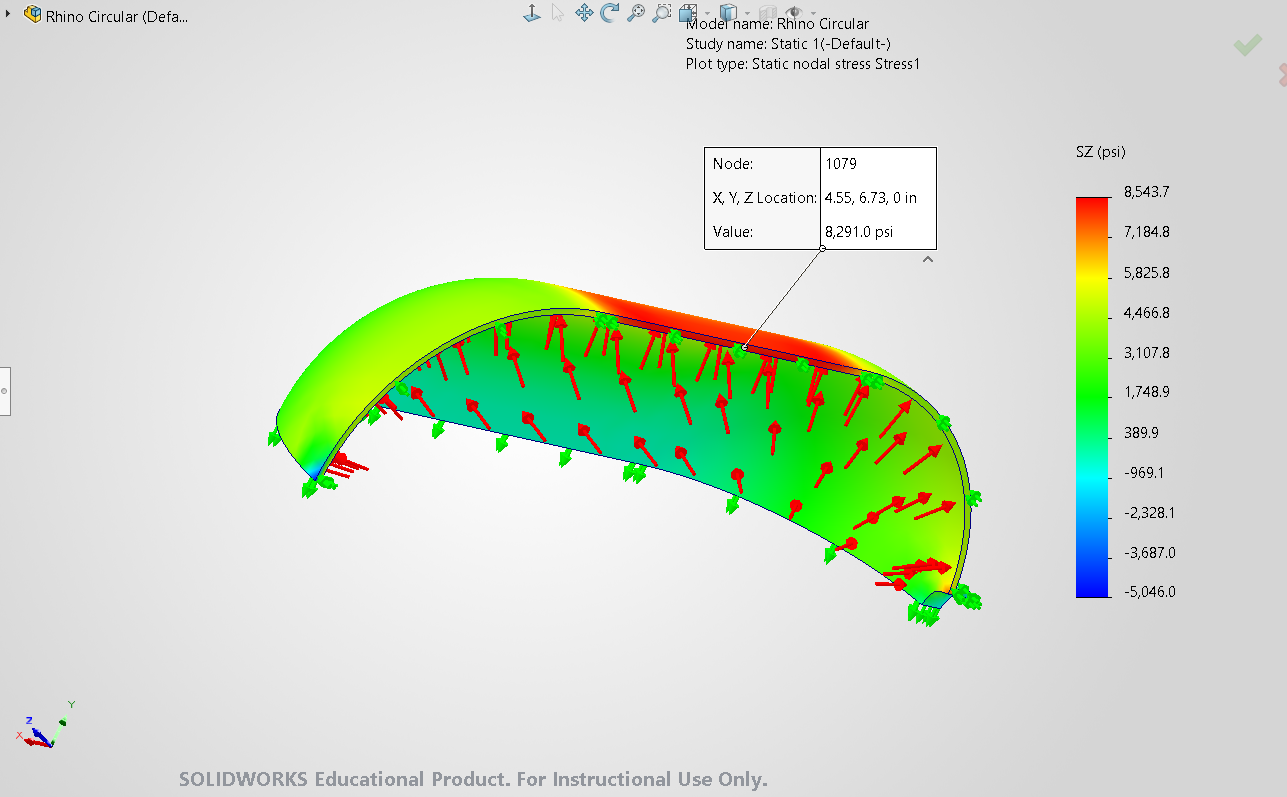
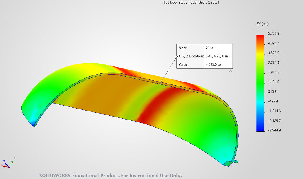
Axial Stress
Hoop Stress
Table (Slide 7)
| Stress Type | Analytical Stress (psi) | SolidWorks Stress (psi) | Percent Difference | | --- | --- | --- | --- | | Hoop Stress | 8,287.5 | 8,219.0 | 0.83% | | Axial Stress | 4,143.75 | 4024.0 | 2.89% |
The axial stress and hoop stress has a difference of 0.83% and 2.89% . This is reasonable because the analytical formula assumes a simple uniform cylinder, while SolidWorks includes the dome geometry, boundary conditions, and stress concentration near the dome-to-cylinder transition.
Slide 8
Flat Dome
The flat dome shows a very high maximum von Mises stress of about 133,687 psi, which is much higher than the 41,000 psi yield strength. This means the flat dome design is not safe under the applied internal pressure.
The flat surface bends more under pressure, creating high stress near the dome-to-cylinder connection.
The maximum stress also occurs around the hole/notch because it disrupts stress flow and creates a stress concentration.
This shows why real gas tanks usually use curved or dished ends instead of flat ends.
Slide 9
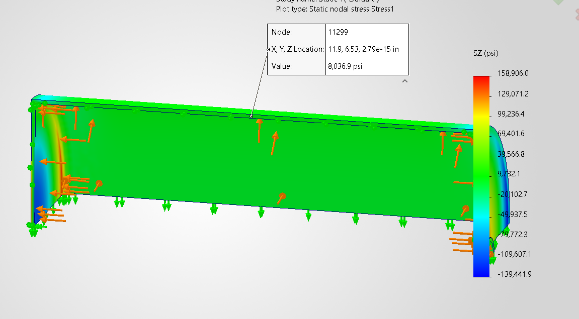
Axial Stress
Hoop Stress
The hoop stress difference is about 3.02%, which is small and shows good agreement with the analytical thin-wall pressure vessel calculation.
The axial stress difference is about 6.00%, which is also reasonable. Small differences can occur because the analytical formula assumes an ideal cylinder, while SolidWorks includes the actual geometry, boundary conditions, and local stress effects. Overall, the SolidWorks results validate the analytical calculation well.
Table (Slide 9)
| Stress Type | Analytical Stress (psi) | SolidWorks Stress (psi) | Difference (psi) | Percent Difference | | --- | --- | --- | --- | --- | | Hoop Stress | 8,287.5 | 8,037.0 | 250.5 | 3.02% | | Axial Stress | 4,143.75 | 3,895.0 | 248.75 | 6.00% |
Slide 10
Conclusion of the study
The curved domes performed better than the flat dome because they distributed pressure more smoothly.
The parabolic dome may be the best option because its smooth curvature reduces stress concentration and creates a better load path.
The circular dome also showed good performance, but the flat dome showed higher bending and stress concentration.
The flat dome is the least suitable design because high stress occurs near the dome-to-cylinder connection and around holes/notches.
Analytical hoop and axial stress values matched reasonably well with SolidWorks results, helping validate the simulation.
Overall, curved or dished dome shapes are safer and more realistic for propane tanks than flat dome shapes.
Real propane tanks usually use curved or dished ends, such as ellipsoidal, torispherical, or hemispherical heads. Curved ends distribute internal pressure more smoothly and reduce stress concentration.
Flat ends are usually avoided because they create higher bending stress and need extra reinforcement.
Slide 11
References
Pressure Vessel Engineering. “Comparison Between Head Types: Hemi, SE, F&D and Flat.”
Inspection for Industry. “Pressure Vessel Heads.”
B.E. Peterson. “Introduction to Different Pressure Vessel Head Types.”
Walmart. “20-lb Steel Propane Tank (5 Gallon) - Empty, No Gauge.” Walmart.
Slide 12
Any questions?
MEMT 508 project