Page 1
Structural performance optimization of Reinforced concrete build- ings with rooftop Telecommunication towers: A location-based analysis BimalOjhaa, SabinKhatria, PrabinPokharela, RasiqueJirela, BinayaJamarkattela and AbhineshKhatrib,∗ aDepartmentofCivilEngineering,InstituteofEngineering,ThapathaliCampus bDepartmentofCivilEngineering,KantipurEngineeringCollege ARTICLE INFO Abstract ThisstudyevaluatesthestructuralresponseofanRCCbuildinginParbat,Nepal,witharooftop Articlehistory: telecommunicationtowerpositionedatvariouslocations.Inourcase,atelecommunication Received 20September2024 towerisalreadylocatedatacertainpositioninthebuilding,andwearetryingtoevaluate Revisedin 3November2024 theoptimalpositionoftelecommunicationtower. ThesiteliesinseismicZoneVasper Accepted 20November2024 IS1893:2016(Part1),indicatingveryhighseismicactivity,andissubjecttosignificant windloads.ThisstudyexaminesthestructuralresponseofanRCCbuildingwitharooftop telecommunicationtower,usingETABS18.1.1andadheringtoIS1893:2016(Part1)seismic designstandards.Theanalysisfocusesontheimpactoftowerplacementoncriticalstructural Keywords: parameters,suchasbaseshear,nodaldisplacement,axialandshearforces,andbendingand Telecommunicationtowerplacement torsionalmoments.Throughfivetowerplacementscenarios,thestudyhighlightssignificant Structuraloptimization findings:a2.37%increaseinbaseshear,upto9.86%variationinaxialforces,andamaximum ETABS 26.60%changeinshearforces. Byisolatingtowerlocationasavariable, thisresearch FiniteElementAnalysis providesdetailedinsightsintohowtowerpositioningaffectsbuildingperformance.Afinite Seismicperformance elementanalysisapproachisused,ensuringaccuracybyexplicitlymodelingRCC-steeltower RCCbuildingresponse interactionsandboltedconnectionoftelecommunicationtowerandRCCstructure. Tower-Structureinteraction ©JIEEThapathaliCampus,IOE,TU.Allrightsreserved isanotableabsenceofcomprehensiveguidelinesfrom
- Introduction regulatorybodiesliketheNationalTelecommunications Citiesandhumancoloniesaregrowingdailyintoday’s Authority(NTA),andalackofstandardizedprotocols environment,whichisforcingourvillagesandagricul- foroptimizingtowerplacement[3]. turalfieldstoshrink. Toavoidneedlessusageofland Recentresearchhasincreasinglyfocusedonthecom- thatisusedfortallconstructionsiscrucial. Itlowers plexitiesofintegratingtelecommunicationtowersinto additionallanduseandexpenses. Inordertosaveland buildingstructures,particularlyrooftopinstallationsin fromneedlessconstruction,towersarenowmovedonto high-riskseismiczones. Thechallengeliesinunder- buildings [1]. The tower on building saves the extra standingthedynamicinteractionsbetweenthesetowers landcostandiftheanalysisandmodelingofthestruc- andsupportingstructures[4]. PioneeringworkbyAssi tureisaccuratewecaneasilyfindoutthesafetyofthe and McClure (2007) highlighted the critical need for structure against lateral loads and against sliding [2]. comprehensiveseismicanalysisofrooftoptelecommu- Buildingsareusedbytowercompaniesfortowers;they nicationtowers[5]. Sincesteeltelecommunicationtow- canberentedoutorusedpermanently. Despitethese ershaveadifferentseismicresponsetoseismicloads advancements,substantialresearchgapspersist. There thanconcretestructures,aninvestigationoftheseismic ∗Correspondingauthor: loadsonsteeltelecommunicationtowersistobecon- [email protected](A.K.) ducted[6]. Moreoverthesafetyagainstseismicloads, andwindloadsismoreimportantwhileanalyzingthe BimalOjha etal./JIEE2024,Vol.7,Issue1. Page131


Page 2
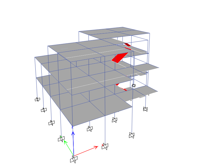
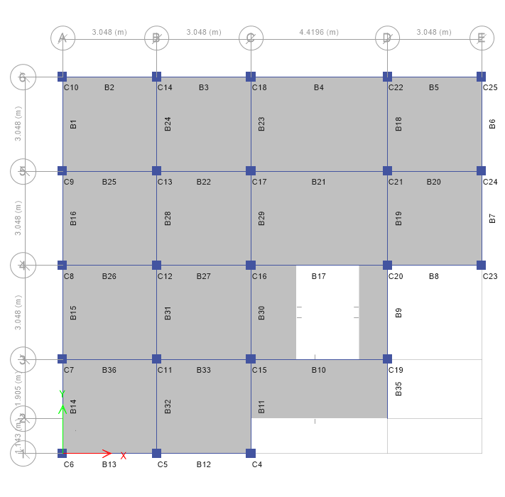
StructuralperformanceoptimizationofReinforcedconcretebuildingswithrooftopTelecommunicationtowers:A location-basedanalysis buildingswithroof-toptelecommunicationtower[7]. • EnvironmentalConditionsAssessment: Detailed Thisstudyprimarilyfocusesonoptimallocationofroof- evaluationofwind,temperature,andotherenvi- top communication tower over a reinforced concrete ronmentalfactorsthatinfluencethestructure. buildinglocatedinhighseismiczone. 3.1.2. Buildingconfiguration ThebuildingtakenintoconsiderationislocatedinPar- batDistrict,Nepal,situatedinSeismicZoneV(asper • G+3storyRCCstructureisconsideredformod- IS:1893:2016part1)[8]. Thebuildingunderstudyisa eling. G+3storyRCCstructure. Materialpropertiesarespec- • Structuralpropertiesaredefinedasfollows: ified for both the concrete (Grade M20, Fe415 grade steelreinforcement)andthesteeltower(structuralsteel, 1. ConcreteGrade: M20(CharacteristicCom- ISA 200x200x25 sections). The building along with pressiveStrength: 20MPa) roof-topcommunicationtowerismodeledusingETABS 2. Reinforcement: Fe415gradesteel 18.1.1. LoadconfigurationsarecalculatedbasedonIS 875,whichincludedeadload,liveload,seismicload, 3. SteelTowerMaterial: Structuralsteel(ISA andwindloadandacomprehensiveloadcombination 200x200x25sections) matrixisestablished. Severaltowerplacementscenar- ios are explored, including central, corner (with four variations),andedgepositioningconfigurations. Apara- metricanalysisisconductedtoexaminebaseshearvari- ations,nodaldisplacements,axialforcedistributions, shearforcecharacteristics,bendingmoments,andtor- sionalmoments. 2. Objectives Thisstudyaimstoevaluatethestructuralresponseofa buildingwitharooftoptelecommunicationtowerplaced invariouslocationsusingETABS.Thespecificobjec- tivesare: • Toanalyzethebuildingwithatelecommunication towerattopusingfiniteelementanalysis. • Tocomparetheresponseofbuildingforvarious locationsoftelecommunicationtowerbasedon Figure1: ETABSmodelofbuilding parameterslikebaseshear,maximumnodaldis- placement,maximumaxial,shearforces,bending moments and torsional moments in beams and columns. 3. Methodology Thisstudyfollowsasystematicapproachtoevaluatethe impactoftelecommunicationtowerplacementonthe structural performance of reinforced concrete (RCC) buildings, specifically focusing on seismic load re- sponses. Themethodologyisdividedintothefollowing keyphases: 3.1. Preliminaryinvestigations 3.1.1. Sitecharacterization • Location: ParbatDistrict,Nepal Figure2: Floorplanofbuilding • SeismicZoneClassification: ZoneV(HighSeis- micRisk) BimalOjha etal./JIEE2024,Vol.7,Issue1. Page132
Page 3
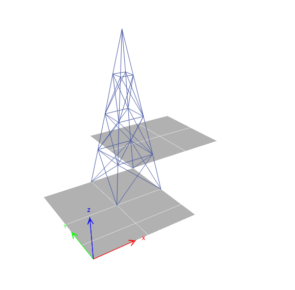
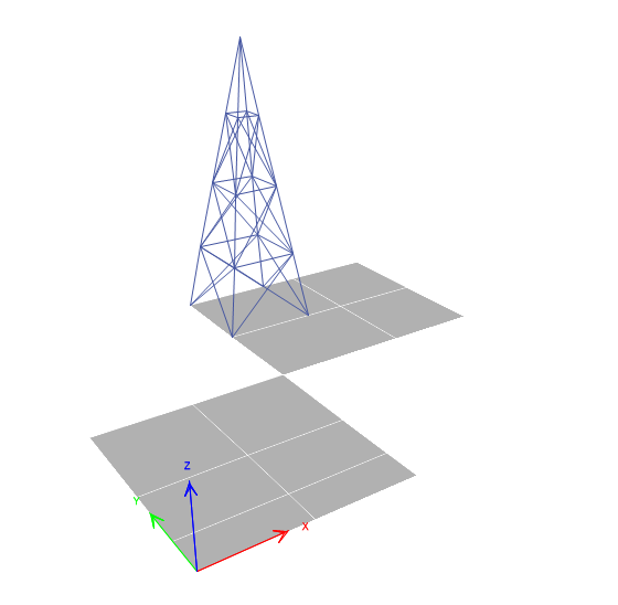
StructuralperformanceoptimizationofReinforcedconcretebuildingswithrooftopTelecommunicationtowers:A location-basedanalysis 3.1.3. Modelingsoftware • ETABS18.1.1isusedtoconductfiniteelement analysis. 3.2. Analyticalframework 3.2.1. LoadConfiguration Thefollowingloadsareappliedbasedonrelevantstan- dards: • DeadLoad: CalculatedusingIS875Part1[9] • LiveLoad: DeterminedaccordingtoIS875Part 2[10] Figure4: Toweratcenter • SeismicLoad: AnalyzedasperIS1893:2016[8] • WindLoad: CalculatedusingIS875Part3[11] 3.2.2. Loadcombinations • 1.5DeadLoad: Standardcombinationforgeneral loadingconditions. • 1.5 Dead Load + 1.5 Live Load: Considered forthetypicaldesignscenario. CombinedSeis- micandWindLoadInteractions: Thestructural modelalsoconsidersinteractionsbetweenseis- mic,andwindloadsundervariousscenarios. Figure5: Toweratcentraledge These load combinations are incorporated into the modeltosimulatereal-worldforcesthataffectthestruc- ture. 3.3. Towerplacementscenarios Fourdistincttowerplacementconfigurationsareevalu- atedtoassesstheirimpactonthebuilding’sstructural response: • CentralPlacement:Thetelecommunicationtower isplacedcentrallyontherooftop. • Corner Placements: Two variations of tower placementsatdifferentcornersoftherooftop. Figure6: Toweratuppercorner • EdgePositioning: Thetowerisplacedalongthe centraledgeofthebuilding. 3.4. Parametricanalysis Thestructuralperformanceisanalyzedbyvaryingkey parametersforeachtowerplacementscenario. These include: • Base Shear Variations: The force transmitted throughthebuilding’sfoundationduringseismic events. • NodalDisplacement: Shiftsinthepositionofthe building’sstructuralnodesduetoloads. • Axial Force Distributions: The distribution of forcesalongthebeamsandcolumns. Figure3: Toweratlowercorner BimalOjha etal./JIEE2024,Vol.7,Issue1. Page133
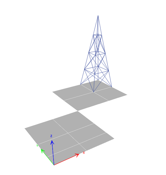
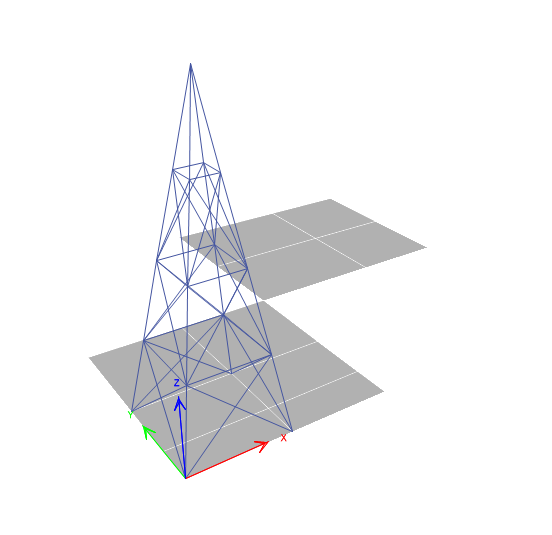
Page 4
StructuralperformanceoptimizationofReinforcedconcretebuildingswithrooftopTelecommunicationtowers:A location-basedanalysis • ShearForceCharacteristics: Analysisofforces Table1: BaseshearinXandYdirection acting in perpendicular directions to structural elements. Opti- Case MaxBaseShear(kN) mum • Bending Moment Analysis: The moment that No. Case causesbendinginbeamsduetoloads. X-Direction Y-Direction • TorsionalMomentEvaluations: Rotationalforces 0 525.3685 525.3685 All onthestructurecausedbyeccentricloads. 1 537.8044 537.8044 have 2 537.8044 537.8044 same 3 537.8044 537.8044 base 3.5. Validationmethodology Theresultsobtainedthroughfiniteelementanalysisare 4 537.8044 537.8044 shear validatedthrough: Remarks: Withtowerontop ofthebuilding,there • Manualcalculationstocheckforconsistencywith wasa2.37%increaseinbaseshear. simulationresults. • Comparison with existing literature on similar structuralstudies. 4. Results Fortheanalysis,fivecaseswereevaluated. Forthefive cases,followingloadcombinationswereusedasperIS code(IS456,Table18)[12]:
- 1.5DL
- 1.5DL+1.5LL Figure7: MaximumNodaldisplacement
- 1.2DL+1.2LL±1.2WL
- 1.5DL±1.5WL
- 0.9DL±1.5WL
- 1.2DL±1.2EL+1.2LL
- 1.5DL±1.5EL
- 0.9DL±1.5EL The first case assessed the building without a tower, whiletheremainingfourcasesassesseddifferenttower locationsontherooftop,asoutlinedbelow: Theabovecaseswereanalyzedbyapplyingalltheload combinations as per IS code (defined above) for the followingparameters. Foralltheparameters,thecase Figure8: MaximumAxialforceinbeam withthelowestvaluewasdefinedastheoptimumcase fortheparticularparameter.
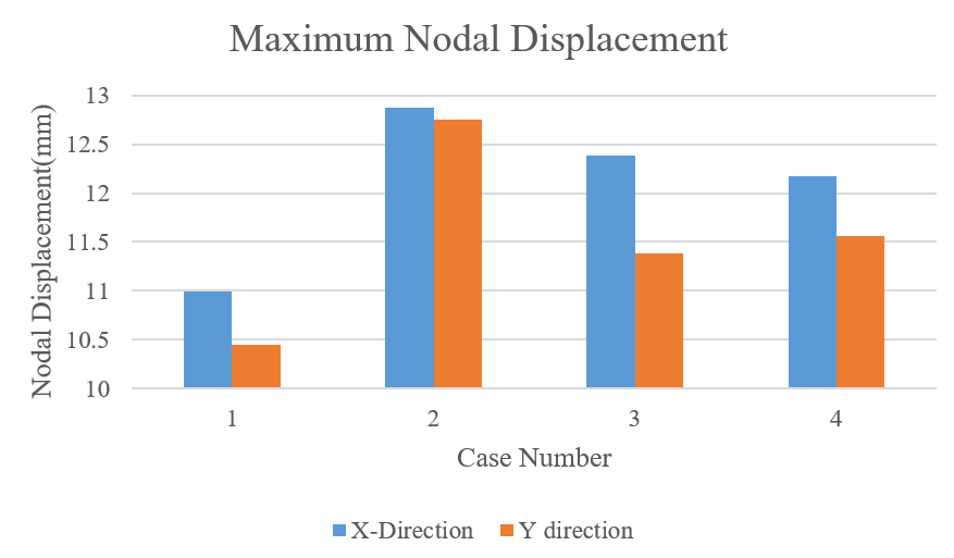
- NodalDisplacement: Themaximumnodaldis- placementsinXandYdirectionvariedwithtower
- Discussion location. Theoptimumcasefornodaldisplace- Thekeyfindingsfromtheanalysisareasfollows: mentwasCase1.
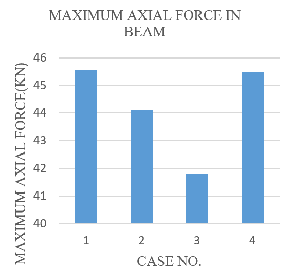
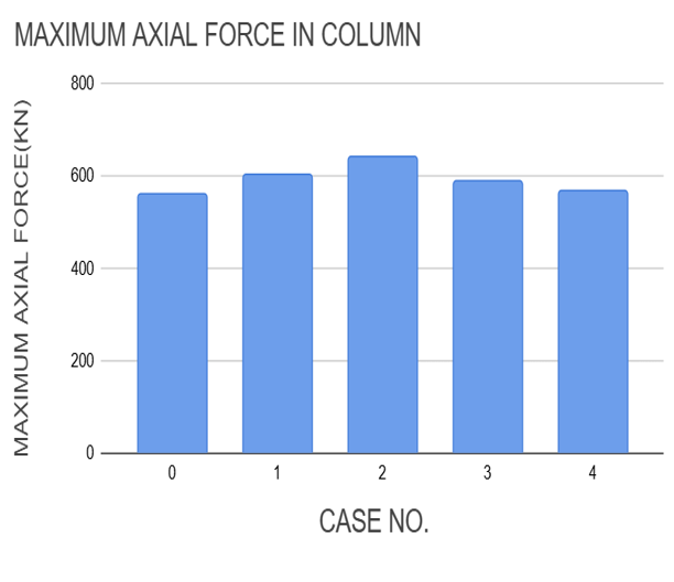
- Base Shear: The addition of the telecommuni- 3. Axial Forces: The axial force in the beam in- cation tower increased base shear by 2.37% in creasedbyupto9.86%(Case1)andincolumn allcaseswhencomparedtothebuildingwithout byupto14.32%(Case2)withthetowerontop telecommunication tower. This increase is be- of the building. Case 3 showed the minimum cause of the additional seismic load due to the axialforceinthebeam,andCase4showedthe telecommunicationtower. minimumaxialforceinthecolumn. BimalOjha etal./JIEE2024,Vol.7,Issue1. Page134
Page 5
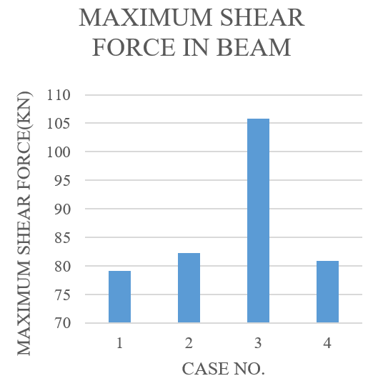
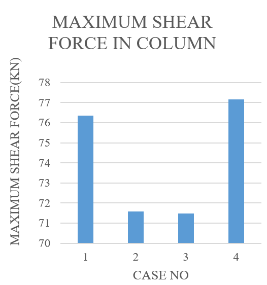
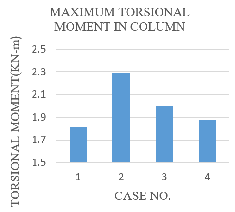
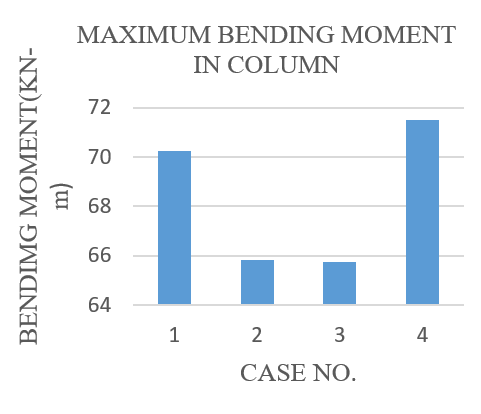
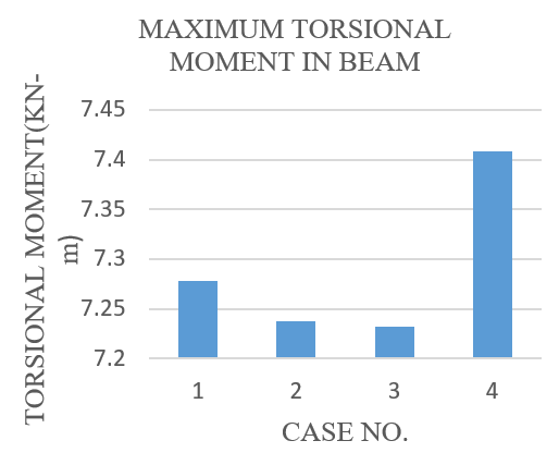
StructuralperformanceoptimizationofReinforcedconcretebuildingswithrooftopTelecommunicationtowers:A location-basedanalysis Table2: MaximumnodaldisplacementinXandYdirection CaseNo. MaxNodalDisplacement(mm) OptimumCase X-Direction Y-Direction 0 10.553 10.532 1 10.996 10.443 2 12.877 12.753 X-direction-Case1,Y-Direction-Case1 3 12.383 11.377 4 12.178 11.563 Remarks: Withtowerontopofthebuilding,themaximumnodaldisplacementisminimumincaseI. Table3: MaximumAxialForceinBeamandColumn MaxAxialForce(KN) OptimumCase CaseNo. Beam Column Force(kN) Storey Label Force(kN) Storey Label Beam Column 0 41.4538 1 B10 562.1814 1 C21 1 45.5416 1 B10 603.4081 1 C15 2 44.1106 3 B29 642.6358 1 C21 Case3 Case4 3 41.7909 2 B17 588.3941 1 C21 4 45.4745 1 B10 566.3138 1 C15 Withthetowerontopofthebuilding,theaxialforceincreasedbyupto9.86%in Remarks: thebeam(Case1)andupto14.32%inthecolumn(Case2). Figure9: MaximumAxialforceinColumn Figure10: MaximumshearforceinBeam 4. ShearForces: Theshearforceinbeamsincreased columnsbyupto5.73%(Case3). Case3showed byupto26.60%(Case1)andincolumnsbyupto minimumtorsionalmomentinbeamandCase1 5.97%(Case1). Case1showedminimumshear showedminimumtorsionalmomentincolumn. forceinbeamandCase3showedtheminimum shearforceincolumn. Theparameterincreasesduetothetelecommunication towerbecausethetoweraddsadditionalmassandheight 5. Bending Moments: The bending moment in tothebuilding,whichinturnincreasestheoverallseis- beamsincreasedbyupto17.26%(Case3)andin micandwindload. Thisadditionalloadincreasesthe columnsbyupto7.70%(Case4). Case2showed forcesandmomentsthatthestructuremustresistdur- minimumbendingmomentinbeamandCase3 ing an earthquake. Specifically, the presence of the showedminimumbendingmomentincolumn. towerchangesthedynamiccharacteristicsofthebuild- 6. Torsional Moments: The torsional moment in ing,leadingtohigherbaseshear,nodaldisplacement, beamsincreasedbyupto3.69%(Case4)andin axialandshearforces,andbendingandtorsionalmo- BimalOjha etal./JIEE2024,Vol.7,Issue1. Page135
Page 6
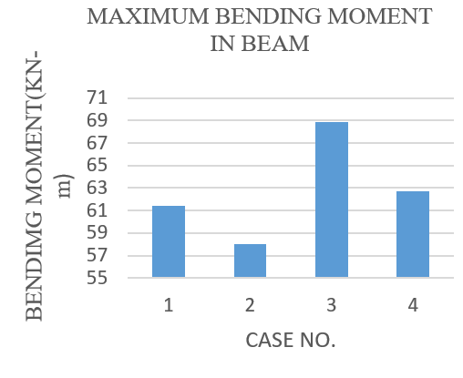
StructuralperformanceoptimizationofReinforcedconcretebuildingswithrooftopTelecommunicationtowers:A location-basedanalysis Table4: MaximumshearforceinBeamandColumn MaxAxialForce(KN) OptimumCase CaseNo. Beam Column Force(kN) Storey Label Force(kN) Storey Label Beam Column 0 77.6576 1 B10 72.0496 1 C19 1 79.0952 1 B10 76.35 1 C19 2 82.2815 1 B10 71.576 1 C19 Case1 Case3 3 105.8023 3 B21 71.4741 1 C19 4 80.9339 1 B10 77.1582 1 C19 Withthetowerontopofthebuilding,theshearforceincreasedbyupto Remarks: 26.60%inbeam(case3)andupto5.97%incolumn(Case1). Table5: Maximumbendingmomentinbeamsandcolumns MaxBendingMoment(KN-m) OptimumCase CaseNo. Beam Column Moment Storey Label Moment Storey Label Beam Column 0 58.7229 1 B10 66.3833 1 C19 1 61.385 1 B10 70.2645 1 C19 2 58.0279 1 B17 65.8339 1 C19 Case2 Case3 3 68.8613 3 B21 65.7372 1 C19 4 62.7541 1 B10 71.4932 1 C19 Withthetowerontopofthebuilding,thebendingmomentincreasedbyupto Remarks: 17.26%inbeam(case3)andupto7.70%incolumn(Case4). Figure12: MaximumbendingmomentinBeam shearforces,bendingmoments,andtorsionalmoments. Figure11: MaximumshearforceinColumn Amongthekeyobservations,itwasfoundthatplacing thetoweratthecenterofthebuildingminimizednodal displacementsinboththeXandYdirections. Similarly, mentsinthestructuralelements. placingthetoweratthecenterofthelongeredgegener- allyresultedinreducedbaseshear,axialforces,shear 6. ConclusionandRecommendation forces,bendingmoments,andtorsionalmoments. The studyalsounderscorestheimpactofadditionalloads Thisstudyanalyzedthestructuralperformanceofan introducedbythetelecommunicationtower,whichin- RCCbuildinginSeismicZoneV,focusingontheimpact creased all structural forces and moments due to the ofarooftoptelecommunicationtowerpositionedatvar- addedseismicmassandaltereddynamiccharacteristics iouslocations. Thefindingsrevealthattheplacementof of the building. These findings highlight the critical thetowersignificantlyinfluencesstructuralparameters, importance of analyzing tower placement during the includingbaseshear,nodaldisplacement,axialforces, BimalOjha etal./JIEE2024,Vol.7,Issue1. Page136
Page 7
StructuralperformanceoptimizationofReinforcedconcretebuildingswithrooftopTelecommunicationtowers:A location-basedanalysis Table6: Maximumtorsionalmomentinbeamsandcolumns MaxTorsionalMoment(KN-m) OptimumCase CaseNo. Beam Column Moment Storey Label Moment Storey Label Beam Column 0 7.1446 2 B35 1.8947 1 C20 1 7.2777 1 B35 1.8151 1 C20 2 7.2373 2 B35 2.2907 1 C20 Case2 Case3 3 7.2317 2 B35 2.0032 1 C20 4 7.4084 1 B35 1.8772 2 C20 Withthetowerontopofthebuilding,thetorsionalmomentincreasedbyupto Remarks: 3.69%inbeam(case3)andupto5.73%incolumn(Case4). Figure13: MaximumbendingmomentinColumn Figure15: MaximumtorsionalmomentinColumn References [1] BhosaleN,PandeyPK.Influenceofhoststructurecharacter- isticsonrooftoptelecommunicationtowers[J]. International JournalofCivilandStructuralEngineering,2012,2(3):737- 748. [2] TakN,ChoudharyM. Analysisofbuildingwithtoweron slopingground[J].InternationalJournalofCurrentEngineering andTechnology,2020. [3] NTA.Website[EB/OL].https://www.nta.gov.np/. [4] ShahHJ,DesaiAK. Seismicanalysisoftalltvtowercon- sideringdifferentbracingsystems[J].InternationalJournalof Engineering,BusinessandEnterpriseApplication,2014:113- Figure14: MaximumtorsionalmomentinBeam 119. [5] RolaA,McClureG.Asimplifiedmethodforseismicanalysis ofrooftoptelecommunicationtowers[J].CanadianJournalof designphasetoensurethestructuralsafetyofbuildings, CivilEngineering,2007. [6] AmiriGG,BarkhordariMA. Seismicbehaviorof4-legged especiallyinhighseismiczones. Centralizedoredge- self-supportingtelecommunicationtowers[C]//13thWorldCon- centralplacementconfigurationsarerecommendedfor ferenceonEarthquakeEngineering.2004. optimizingstructuralperformance. [7] McClure G, Georgi L, Assi R. Seismic considerations for telecommunicationtowersmountedonbuildingrooftops[C]// 13thWorldConferenceonEarthquakeEngineering.Vancouver, Thisresearchcontributesvaluableinsightsforstructural B.C.,Canada,2004. optimization and resilience in similar configurations. [8] BIS.Criteriaforearthquakeresistantdesignofstructures-part Futurestudiescouldfocusonexperimentalvalidation 1generalprovisionsandbuildings[M].2016. [9] BIS.Codeofpracticefordesignloads(otherthanearthquake) andincorporateadditionaldynamicfactors,suchassoil- forbuildingsandstructures(part1deadloads)[M].1987. structureinteractionandfatigueanalysis,tobuildupon [10] BIS.Codeofpracticefordesignloads(otherthanearthquake) thefindings. forbuildingsandstructures(part2liveloads)[M].1987. [11] BIS.Codeofpracticefordesignloads(otherthanearthquake) forbuildingsandstructures(part3windloads)[M].1987. [12] BIS.Plainandreinforcedconcrete-codeofpractice[M].2000. BimalOjha etal./JIEE2024,Vol.7,Issue1. Page137
ResearchGate